3-Way Ball Valve Motorized
Description
TECHNICAL DATA SHEET
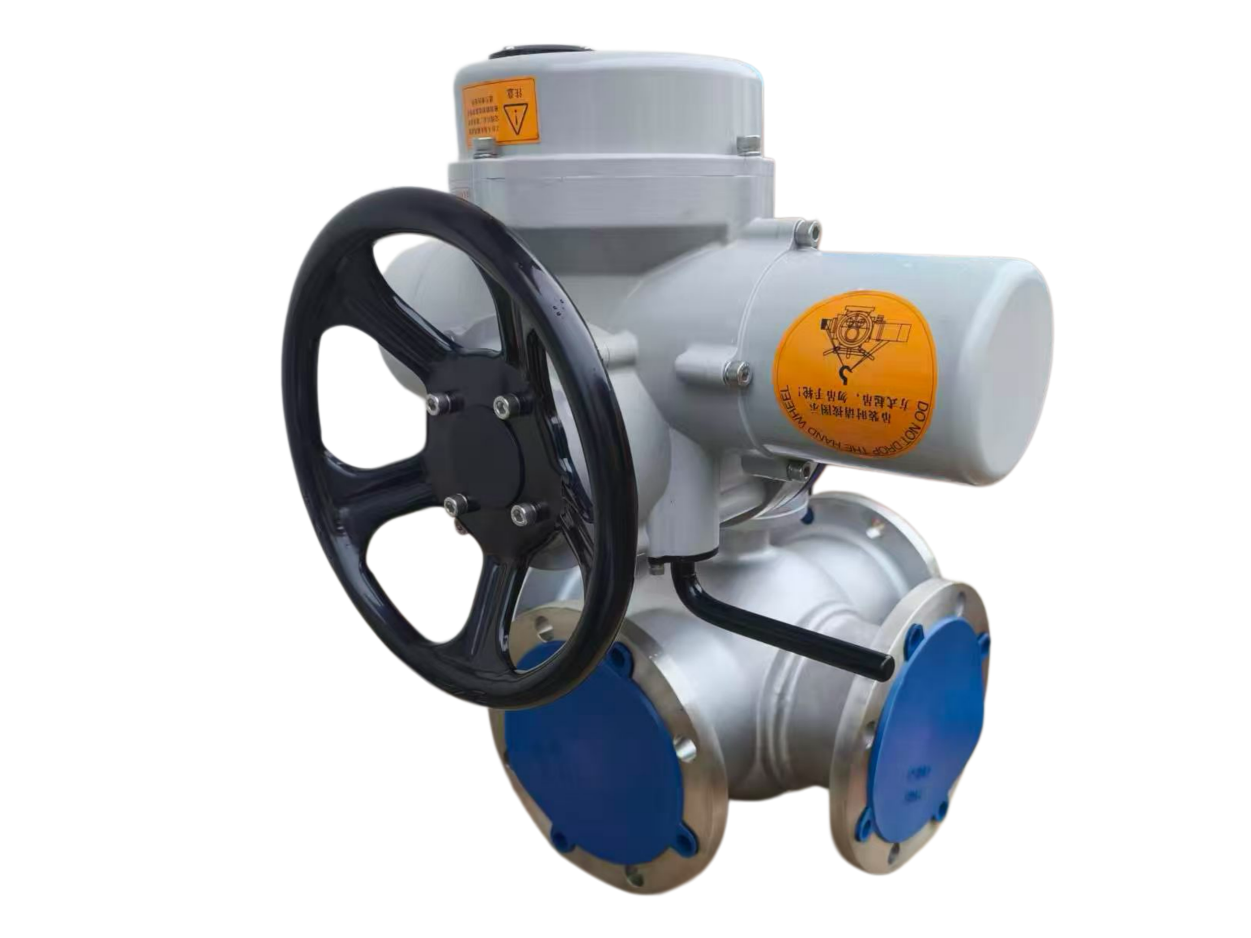
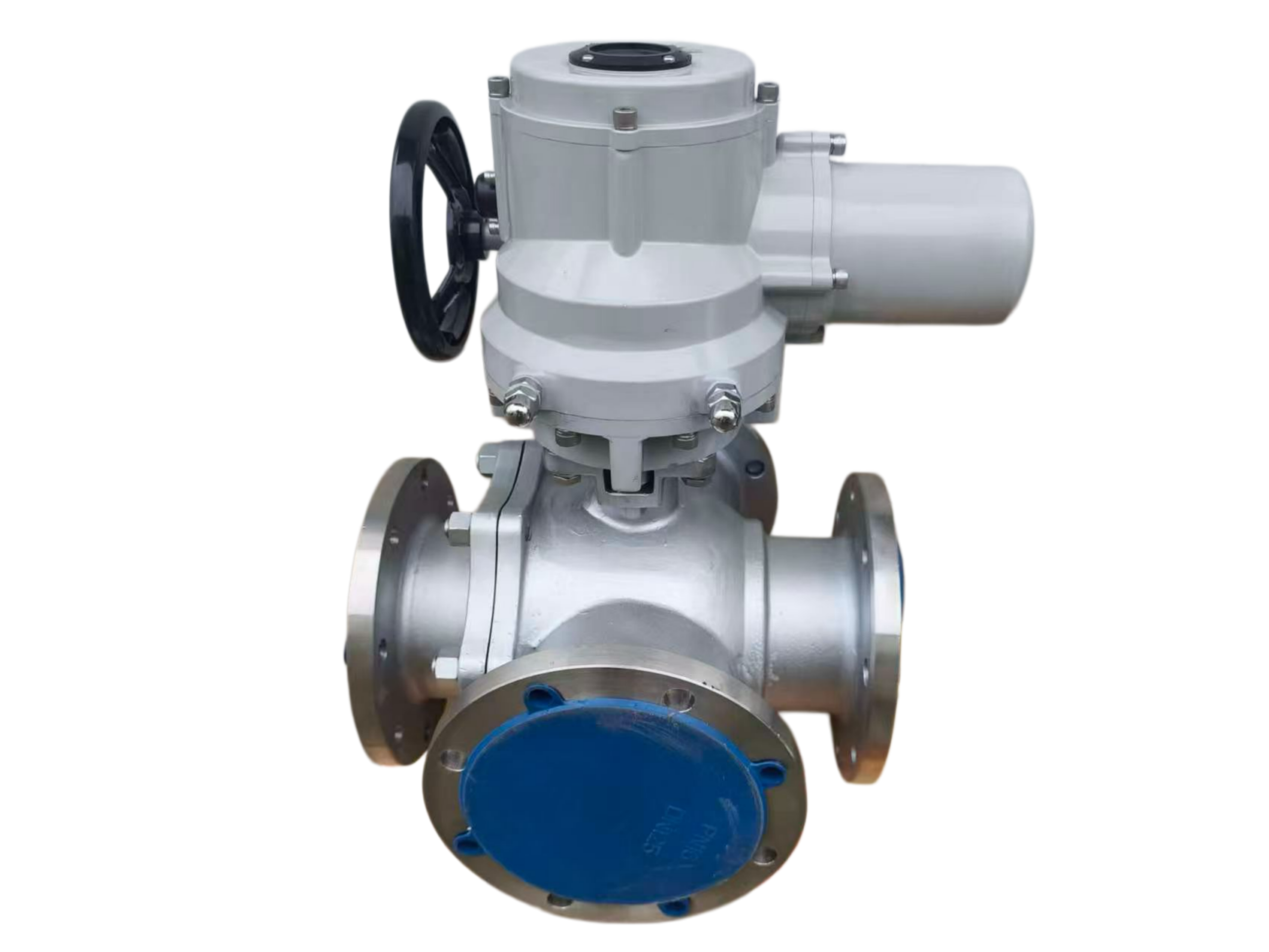
Motorized 3‑Way Ball Valve
L‑Port / T‑Port · Electric Actuated · Multiport Flow Control
1. PRODUCT DESCRIPTION
The Motorized 3‑Way Ball Valve is a multiport quarter‑turn valve designed for flow diversion, mixing, or shut‑off in three‑pipe systems. With a specially ported ball core (L‑port or T‑port configuration), the valve enables selective switching of media between two outlet ports or merging of two inlet streams into a common outlet, all within a single compact body.
The electric actuator provides automated, remote‑controlled operation, making this valve ideal for HVAC, chemical dosing, heat exchanger bypass, water treatment, and industrial process control. By replacing multiple two‑way valves, the 3‑way ball valve simplifies piping, reduces installation footprint, and lowers system cost while maintaining bubble‑tight shut‑off and reliable performance.
2. DESIGN FEATURES
| Feature | Description |
|---|---|
| Valve Type | 3‑way multiport ball valve (L‑port or T‑port) |
| Port Configuration | L‑port (diversion / 2‑position switching) or T‑port (mixing / blending / full bypass) |
| Operation | 90° or 180° rotation (depending on port design) achieves flow path change |
| Shut‑off | Bidirectional bubble‑tight sealing (zero leakage) |
| Stem Design | Anti‑blowout stem with double O‑ring seals |
| Actuator Mounting | ISO 5211 direct mounting interface |
| Manual Override | Built‑in manual override (handwheel or hexagon) for emergency operation |
| Maintenance | Low maintenance; PTFE seats and seals offer long cycle life |
3. TECHNICAL SPECIFICATIONS
3.1 General Parameters
| Parameter | Specification |
|---|---|
| Size Range | DN15 – DN300 (½” – 12″) |
| Pressure Ratings | PN16 – PN100 / Class 150 – Class 600 |
| Design Standards | API 6D, ISO 17292, ASME B16.34, BS 5351 |
| Face‑to‑Face Dimensions | ASME B16.10, DIN 3202 |
| End Connections | Flanged (RF, RTJ), threaded (BSP/NPT), socket weld, butt weld |
| Top Flange | ISO 5211 |
3.2 Operating Conditions
| Parameter | Specification |
|---|---|
| Maximum Working Pressure | 10.0 MPa (100 bar) / Class 600 |
| Operating Temperature (Valve) | -40°C to +450°C (seat‑material dependent) |
| Ambient Temperature (Actuator) | -20°C to +60°C |
| Applicable Media | Water, oil, steam, gas, air, chemical fluids, slurries (with compatible trim) |
4. MATERIAL SPECIFICATION
| Component | Material Options | Grade / Standard |
|---|---|---|
| Body | Carbon Steel, Stainless Steel, Ductile Iron | WCB, CF8 (304), CF8M (316), CF3 (304L), CF3M (316L) |
| Ball Core | Stainless Steel | F304, F316, F304L, F316L |
| Stem / Shaft | Stainless Steel | AISI 304, 316, 410 |
| Seat | PTFE, RPTFE, PPL, PEEK, Nylon | |
| Seat (Standard) | PTFE: -9°C to +180°C | |
| Seat (High Temp.) | PPL: -29°C to +250°C | |
| O‑Ring Seals | EPDM, FKM (Viton®), NBR | |
| Body Coating | Epoxy coating (optional) |
5. PORT CONFIGURATIONS
| Configuration | Flow Path Description | Typical Application |
|---|---|---|
| L‑Port | The ball has two passages that connect adjacent ports in a 90° rotation; switches flow from one common inlet to either of two outlets (or vice versa). | Flow diversion / selector valve – e.g., switching feed between two heat exchangers. |
| T‑Port | The ball has three interconnected passages; can mix two inlet streams into one outlet, or divert one inlet to either outlet, or provide full bypass. | Blending, mixing, or bypass control in HVAC and process lines. |
Standard rotation: 90° for L‑port; 180° for full T‑port functionality (some designs use 90° for T‑port partial opening).
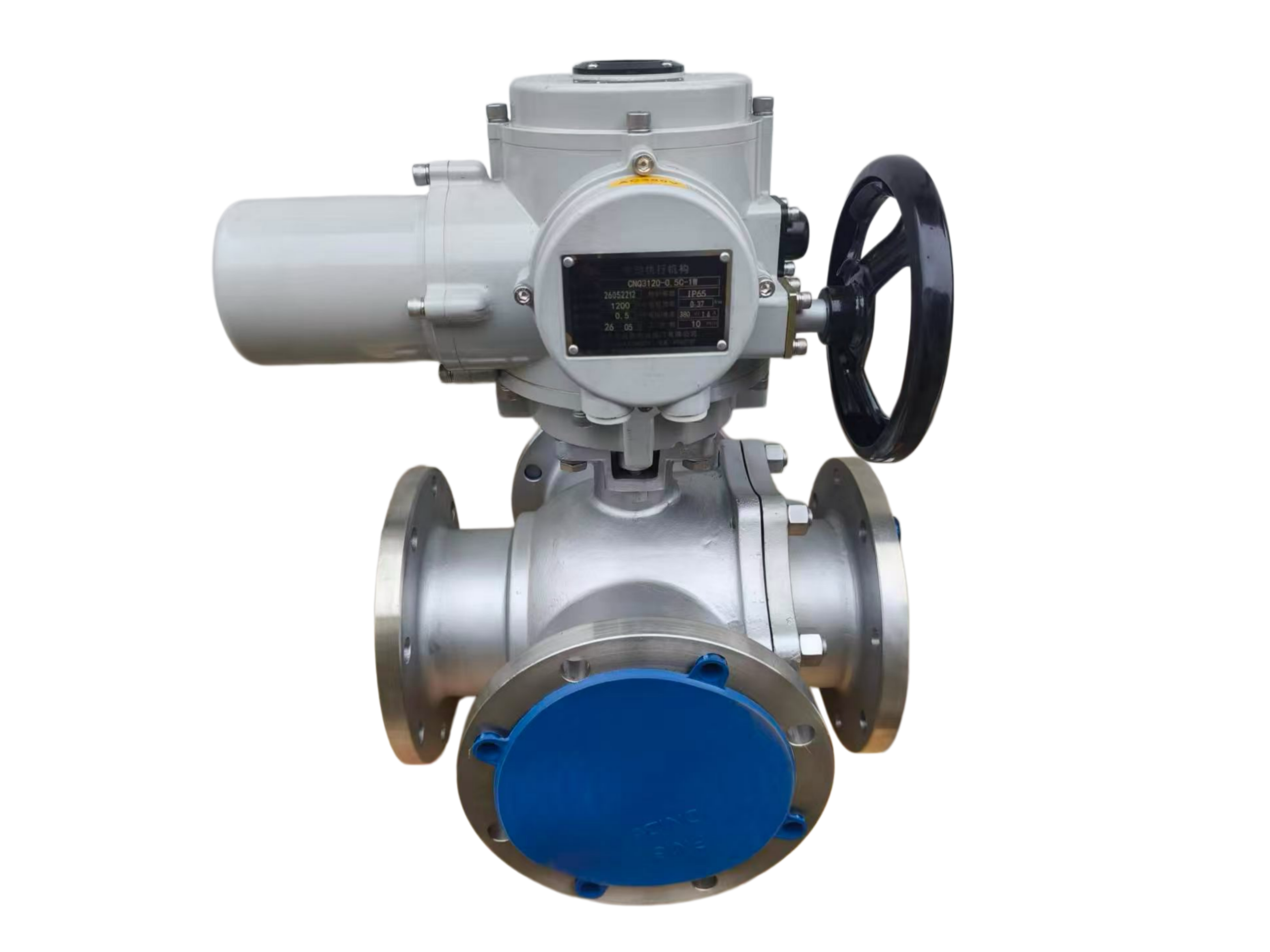
6. ELECTRIC ACTUATOR SPECIFICATIONS
| Parameter | Specification |
|---|---|
| Actuator Type | 90° / 180° quarter‑turn electric rotary actuator |
| Torque Range | 50 Nm to 4,000 Nm (442 to 35,398 in‑lb) |
| Mounting Standard | ISO 5211 direct mounting |
| Supply Voltage | AC110V, AC220V, AC380V, AC240V, DC12V, DC24V |
| Control Options | ON/OFF (open‑close); Modulating (4‑20mA, 0‑10V, 1‑5V); MODBUS, PROFIBUS (optional) |
| Feedback Signals | Limit switches (open/closed), 4‑20mA position feedback, potentiometer |
| Protection Class | IP65 (standard); Explosion‑proof Ex II BT4 available |
| Cycle Time (90°) | 15 – 100 seconds (torque dependent) |
| Manual Override | Handwheel or hexagon drive |
| Duty Cycle | S2: 15 min (short‑time duty) |
7. PERFORMANCE & TESTING
| Test | Standard | Requirement |
|---|---|---|
| Body Shell Test | API 598 / ISO 5208 | 1.5 × rated pressure, no visible leakage |
| Seat Leak Test | API 598 / API 6D / ISO 5208 | Bubble‑tight shut‑off (Rate A) |
| Fire‑safe Test | API 607 / API 6FA | Available upon request |
| Anti‑static Design | API 607 / API 6FA | Standard (spring‑loaded ball/stem) |
| Pressure‑Temperature Rating | ASME B16.34 | Per class rating chart |
8. DIMENSIONS (Typical – Flanged Type)
Dimensions are for reference only. Contact factory for certified drawings.
| DN | Face‑to‑Face (mm) | Approx. Weight (kg) |
|---|---|---|
| 15 | — | — |
| 20 | — | — |
| 25 | — | — |
| 40 | — | — |
| 50 | — | — |
| 80 | — | — |
| 100 | — | — |
| 150 | — | — |
| 200 | — | — |
| 250 | — | — |
| 300 | — | — |
Face‑to‑face dimensions conform to ASME B16.10 / DIN 3202 for 3‑way ball valves.
9. APPLICATIONS
-
HVAC systems – changeover between chillers / boilers, bypass control
-
Chemical & petrochemical – process stream diversion, reactor feed switching
-
Water & wastewater treatment – filter backwash, sample line switching
-
Power generation – cooling water selection, fuel oil switching
-
Food & beverage – CIP (clean‑in‑place) routing, product diversion
-
Pharmaceutical – sterile fluid direction control
-
Oil & gas – manifold switching, wellhead test separation
10. OPTIONS & CUSTOMIZATIONS
| Option | Details |
|---|---|
| Body Materials | WCB, CF8 (304), CF8M (316), CF3 (304L), CF3M (316L) |
| Ball Materials | A105, F304, F316, F316L |
| Seat Materials | PTFE, RPTFE, PPL, NYLON, PEEK, metal‑seated |
| End Connections | Flanged (RF, RTJ), threaded (BSP/NPT), socket weld, butt weld |
| Actuator Type | ON/OFF, Modulating (4‑20mA), Intelligent, Explosion‑proof |
| Feedback | Limit switches, 4‑20mA position transmitter, potentiometer |
| Extended Stem | For buried / insulated installations |
| Fire‑safe | API 607 / API 6FA certified |
| Anti‑static | Standard |
| Special Cleaning | For oxygen service or ultra‑pure applications |
11. APPLICABLE STANDARDS
| Standard | Description |
|---|---|
| API 6D | Pipeline valves (ball valves) |
| ISO 17292 | Metal ball valves for petroleum, petrochemical and allied industries |
| ASME B16.34 | Valves — Flanged, threaded, and welding end |
| ASME B16.10 | Face‑to‑face dimensions |
| ASME B16.5 | Flange dimensions |
| API 598 | Valve inspection and testing |
| ISO 5208 | Pressure testing of industrial valves |
| EN 12266‑1 | Industrial valves — Testing of valves |
| API 607 / API 6FA | Fire‑safe testing |
| BS 5351 | Specification for steel ball valves |
| NACE MR 01‑75 | Sulfide stress cracking resistant materials (optional) |
This technical data sheet is for general reference only. Specifications are subject to change without prior notice. For specific project requirements, please consult the manufacturer or our technical support team.


