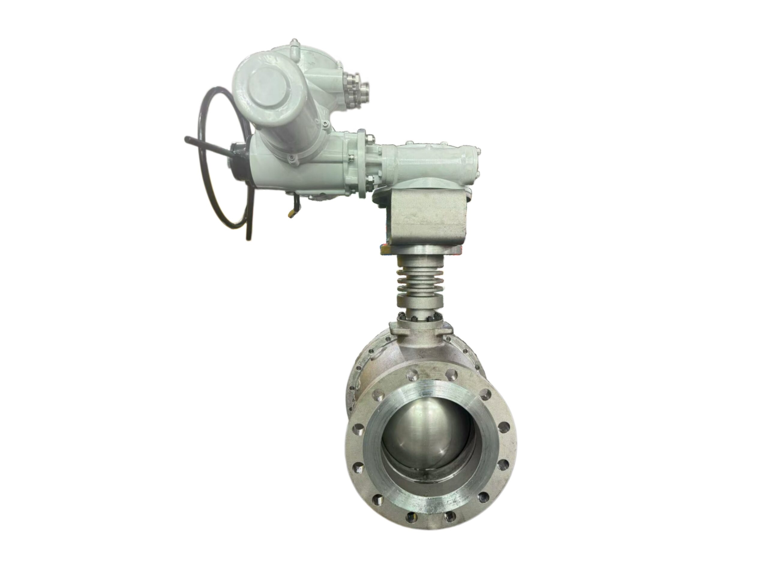
Motorized Ball Valve – High Temperature Service
Description
TECHNICAL DATA SHEET
Motorized Ball Valve – High Temperature Service
Series HMBV-HT
1. PRODUCT DESCRIPTION
The Series HMBV-HT motorised ball valve integrates a full-bore, high-temperature ball valve with a robust electric actuator. Engineered for reliable isolation and control of hot fluids, steam, and thermal oils, it is ideal for applications where manual operation is impractical or remote automation is required. The valve is offered in 2-way and 3-way configurations with a choice of high-performance seating materials to withstand continuous high temperatures.
2. KEY FEATURES
-
High Temperature Capability: Metal or reinforced PTFE seats for continuous service up to +300 °C (+572 °F).
-
Full Bore Design: Minimal pressure drop; piggable in 2-way straight pattern.
-
Electric Actuator: Compact, weatherproof housing with manual override handwheel.
-
Safety Function: Spring-return fail-safe option available (on/off or modulating).
-
Flexible Control: On/Off, 3-point floating, or modulating (4-20 mA / 0-10 V) control modes.
-
Visual Position Indication: High-visibility dome indicator and optional feedback switches.
-
Anti-static & Blow-out Proof Stem: Safety features as standard.
-
Heating Jacket: Optional steam/liquid jacket for temperature maintenance.
3. TECHNICAL SPECIFICATIONS
3.1 VALVE SECTION
| Parameter | Specification |
|---|---|
| Valve Type | Full bore, floating or trunnion-mounted ball valve (DN15–DN100 floating; larger on request) |
| Body Style | 2-Way (straight) / 3-Way (L-port or T-port) |
| Nominal Diameter (DN) | DN15 to DN100 (1/2″ to 4″) |
| Pressure Rating | PN16, PN25, PN40 (Class 150, 300) |
| Body Material | Stainless Steel 316 (1.4408), SS304 (1.4308), Carbon Steel WCB |
| Ball Material | SS316 / SS304 |
| Stem Material | SS316, blow-out proof design |
| Seat Material (Standard) | Reinforced PTFE (RTFE) – up to +200 °C |
| Seat Material (High Temp) | Metal seated (Stellite 6 or similar hard facing) – up to +300 °C |
| Seal Packing | Graphite / PTFE-Graphite combination |
| Connection Ends | Flanged (EN 1092-1, ASME B16.5) / Threaded (BSPP, NPT) / Butt Weld (BW) |
| Leakage Rate (Seat) | Metal seated: Class IV (IEC 60534-4); RTFE: Class VI (bubble-tight) |
| Temperature Range | -20 °C to +300 °C (depending on seat & seal selection) |
| Flow Characteristic | On/Off; Equal % (for 3-way diverting) with V-ball option |
3.2 ACTUATOR SECTION
| Parameter | Specification |
|---|---|
| Actuator Type | Electric quarter-turn, asynchronous motor |
| Supply Voltage | 24 V AC/DC, 110–240 V AC, 380 V AC (50/60 Hz) |
| Duty Cycle | S2 15 min (on/off); S4 30–50% (modulating) |
| Torque Range | 20 Nm to 2000 Nm (higher on request) |
| Operating Angle | 90° (adjustable mechanical end-stops) |
| Operating Speed | 15 s / 90° (standard, others on request) |
| Control Mode | On/Off, 3-point (open/close), modulating (4-20 mA / 0-10 V) |
| Enclosure Protection | IP67 (standard), IP68 optional |
| Ambient Temperature | -20 °C to +60 °C |
| Explosion Protection | ATEX II2G Ex db IIB T4 (optional) |
| Manual Override | Declutchable handwheel for emergency operation |
| Visual Indicator | Dome-type position indicator (red/green) |
| Feedback | 2 x SPDT auxiliary microswitches (standard); 4-20 mA retransmission optional |
| Heater/Anti-condensation | Internal heater standard for actuators in high humidity environments |
| Conduit Entries | 2 x M20 x 1.5 (or NPT adapters) |
| Mounting Base | ISO 5211 flange pattern |
4. MATERIAL COMPATIBILITY & TEMPERATURE LIMITS
| Seat/Seal Configuration | Max. Fluid Temp. | Recommended Media |
|---|---|---|
| RTFE + PTFE/Graphite packing | +200 °C | Steam (low pressure), hot water, thermal oil (<200 °C) |
| Metal seated (Stellite) + pure Graphite packing | +300 °C | Superheated steam, hot gases, thermal oils, high-temp chemicals |
Note: For continuous high-temperature service above 200 °C, an extended stem / cooling fin design is strongly recommended to protect the actuator from radiated heat. Consult factory for actuator bracket insulation.
5. TYPICAL DIMENSIONS (Flanged 2-Way, PN16)
| DN | L (mm) | H (mm) | Actuator Model | Approx. Weight (kg) |
|---|---|---|---|---|
| 15 | 130 | 185 | MA-20 | 4.5 |
| 20 | 150 | 190 | MA-20 | 5.0 |
| 25 | 160 | 200 | MA-40 | 6.5 |
| 40 | 200 | 225 | MA-60 | 10.0 |
| 50 | 230 | 250 | MA-100 | 14.0 |
| 65 | 290 | 275 | MA-200 | 20.0 |
| 80 | 310 | 300 | MA-300 | 25.0 |
| 100 | 350 | 340 | MA-500 | 38.0 |
Dimensions for 3-way and high-temp extended stem versions on request. L = face-to-face, H = centerline to actuator top.
6. WIRING DIAGRAM (Typical On/Off with Feedback)
Terminal Block:
1 - L (Line / Phase)
2 - N (Neutral)
3 - Earth (PE)
4 - Open command
5 - Close command
6 - Common feedback
7 - NO (open position)
8 - NC (closed position)
See specific actuator manual for modulating wiring and fieldbus options (Modbus, Profibus).
7. ORDERING CODE BREAKDOWN
HMBV-HT – A – B – C – D – E – F
-
A – Body Material: 4 = SS304, 6 = SS316, C = WCB carbon steel
-
B – Size: DN15 = 015, DN25 = 025, DN50 = 050 etc.
-
C – Connection: F = Flanged, T = Threaded, W = Butt Weld
-
D – Seat Type: R = Reinforced PTFE (≤200 °C), M = Metal Seated (≤300 °C)
-
E – Actuator Function: ON = On/Off, MO = Modulating, FS = Fail-safe spring return
-
F – Voltage: 24 = 24 V AC/DC, 240 = 110–240 V AC, 380 = 380 V AC
Example:
HMBV-HT-6-050-F-M-ON-240
Motorised Ball Valve, SS316, DN50, Flanged, Metal seated, On/Off, 110–240 V AC actuator.
8. OPTIONS & ACCESSORIES
-
Extended stem / cooling fins for actuator protection
-
Steam/liquid heating jacket
-
Cavity-filler seat (for suspended solids)
-
V-port control ball for precise flow modulation
-
Declutchable gearbox for high torque
-
ATEX actuator for hazardous zones
-
Fieldbus communication (Modbus RTU, Profibus DP)
-
Customer-specific flange drilling
DISCLAIMER: This data sheet is for general information only. The manufacturer reserves the right to modify specifications without prior notice. For critical applications, please confirm a detailed specification with our engineering department.


