4-Way Ball Valve Motorized
Description
TECHNICAL DATA SHEET
Motorized 4-Way Ball Valve
Multiport Flow Control · Electric Actuated
1. PRODUCT DESCRIPTION
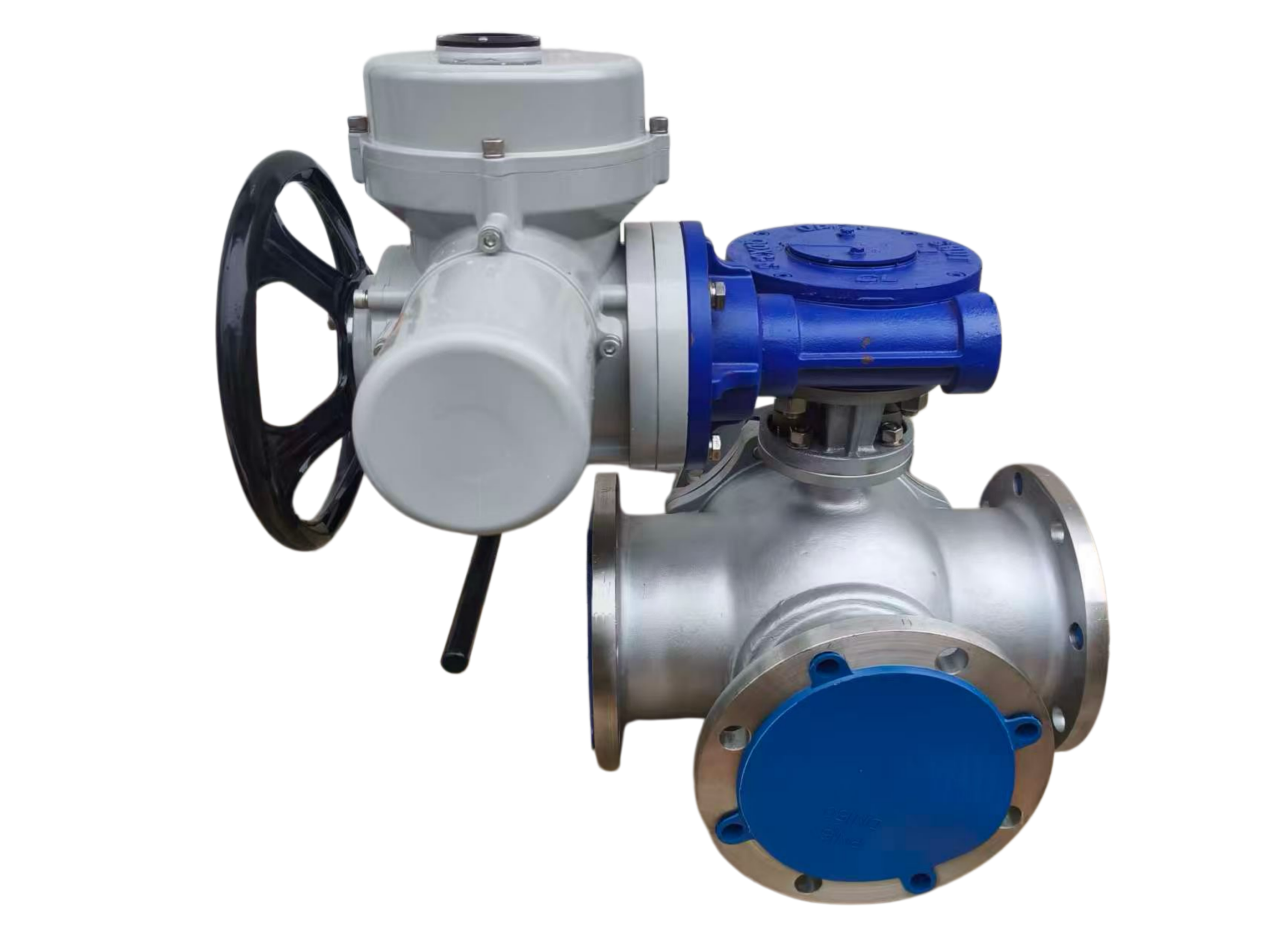
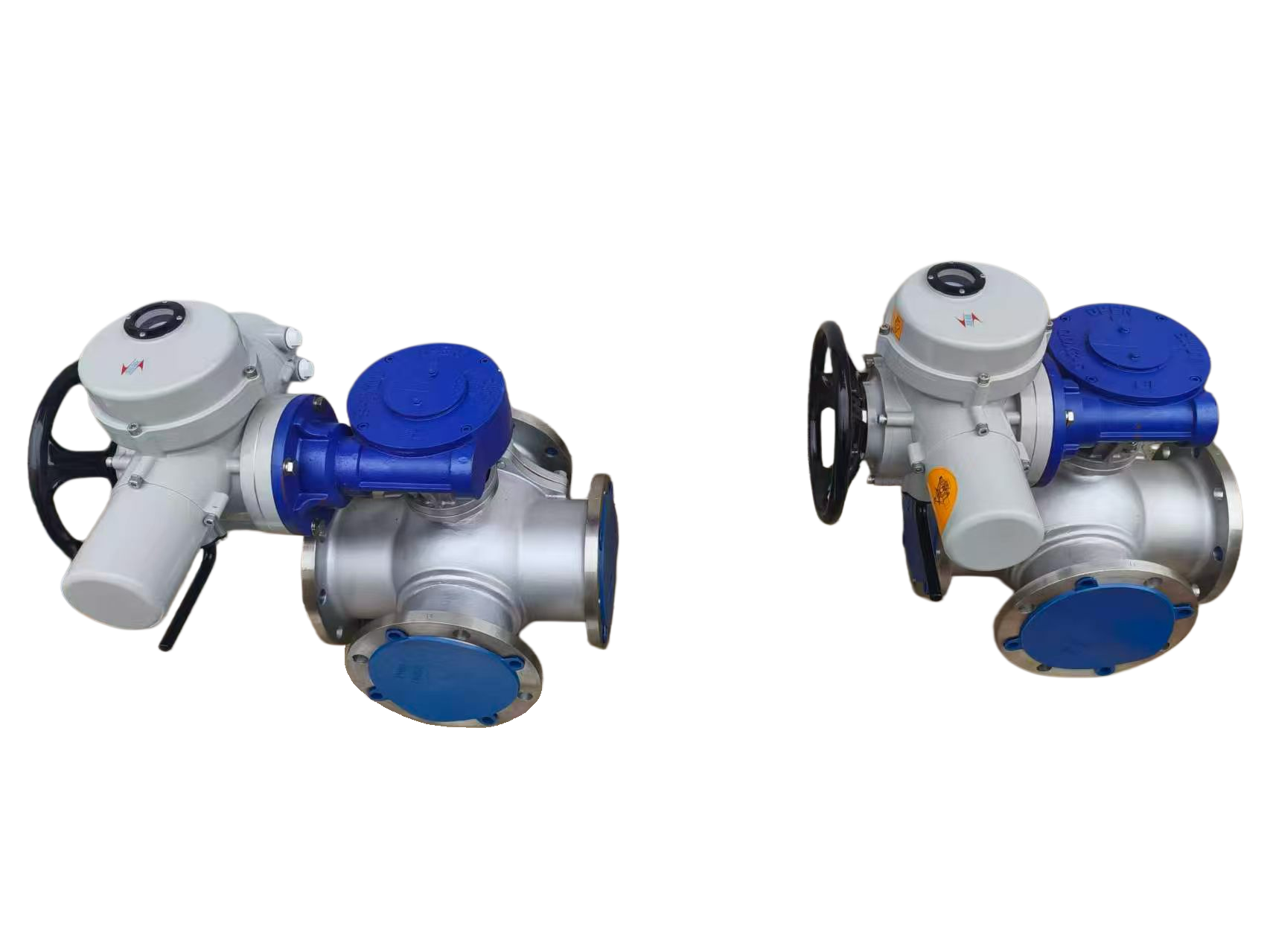
The Motorized 4-Way Ball Valve is a multiport quarter-turn rotary valve designed for directional flow control, flow diversion, and media mixing in complex piping systems. Featuring a four-port body with a specially configured ball core (X / LL port design), this valve enables simultaneous switching of flow paths between two media with a single 90° rotation.
The electric actuator provides automated, remote-controlled operation, making this valve ideal for power station cooling water systems, petrochemical switching applications, HVAC, and industrial process control where reliable flow redirection is essential. The motorized 4-way ball valve replaces multiple two-way valves, simplifying piping layouts, reducing installation space, and lowering overall system costs.
2. DESIGN FEATURES
| Feature | Description |
|---|---|
| Valve Type | 4-way multiport ball valve (X / LL port configuration) |
| Flow Path Design | Ball core with two internal passages arranged in X-shape; four channels arranged on equatorial circumferential section of the sphere |
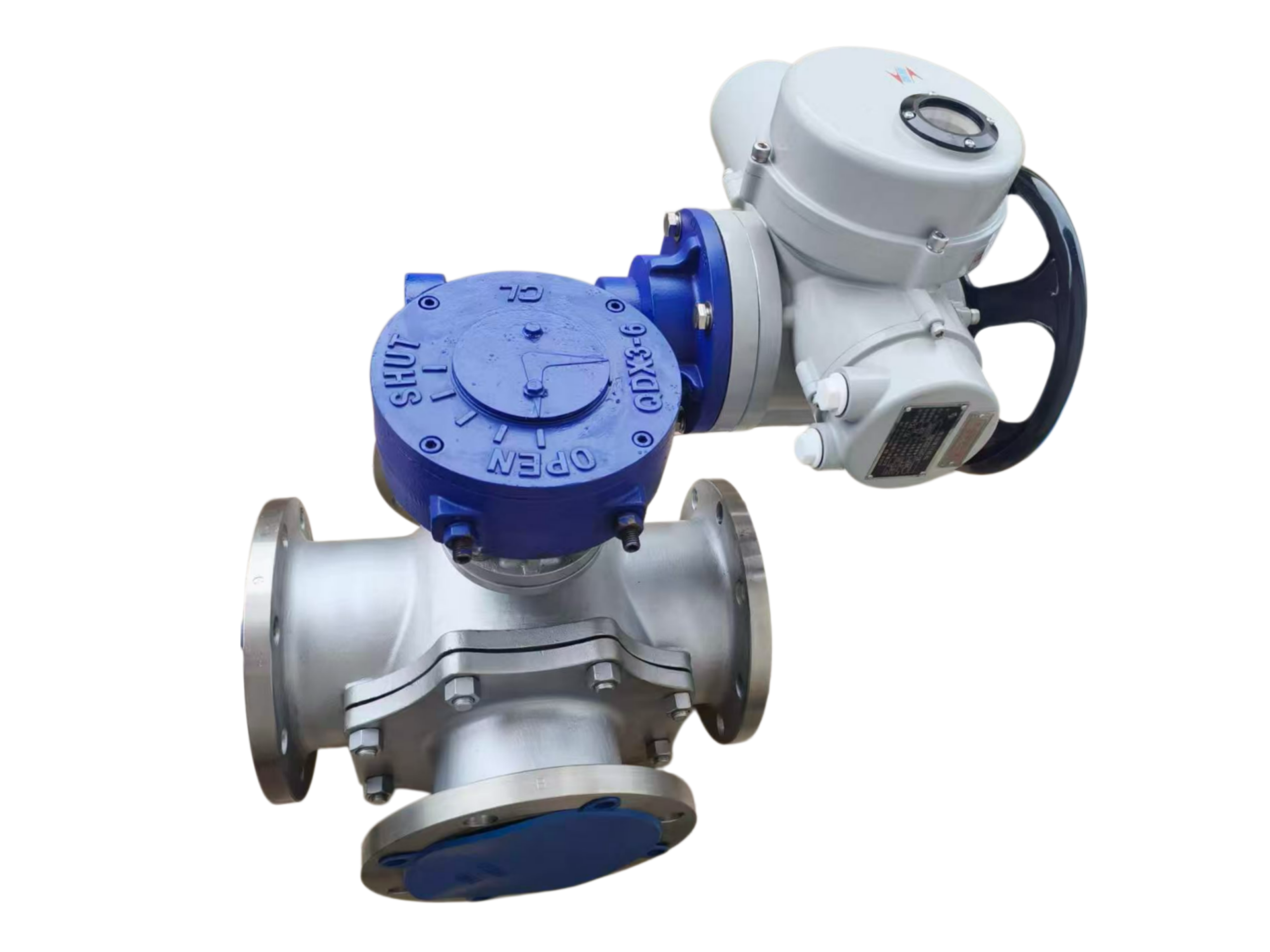
| Operation | 90° rotation switches flow direction between two media simultaneously |
| Port Configuration | L-port, Double L-port (X-port), or T-port available |
| Shut-off | Bidirectional bubble-tight sealing |
| Stem Design | Anti-blowout stem with double O-ring seals for added protection |
| Actuator Mounting | ISO 5211 direct mounting |
| Manual Override | Built-in manual override mechanism for operation during power interruption |
| Maintenance | Compact design with reduced maintenance requirements |
3. TECHNICAL SPECIFICATIONS
3.1 General Parameters
| Parameter | Specification |
|---|---|
| Size Range | DN15 – DN300 (½” – 12″) |
| Pressure Ratings | PN16 – PN100 / Class 150 – Class 600 |
| Design Standards | API 6D, ISO 17292, BS 5351, ASME B16.34 |
| Face-to-Face Dimensions | ASME B16.10, DIN 3202 |
| End Connections | Flanged (RF, RTJ), threaded (BSP, NPT), socket weld, butt weld |
| Top Flange | ISO 5211 |
3.2 Operating Conditions
| Parameter | Specification |
|---|---|
| Maximum Working Pressure | 10.0 MPa (100 bar) / Class 600 |
| Operating Temperature (Valve) | -40°C to +450°C (depending on seat material) |
| Ambient Temperature (Actuator) | -20°C to +60°C |
| Applicable Media | Water, oil, steam, gas, air, liquid, dust, slurry, solid particle media |
4. MATERIAL SPECIFICATION
| Component | Material Options | Grade / Standard |
|---|---|---|
| Body | Carbon Steel, Stainless Steel, Ductile Iron | WCB, CF8 (304), CF8M (316), CF3 (304L), CF3M (316L) |
| Ball Core | Stainless Steel | F304, F316, F304L, F316L |
| Stem / Shaft | Stainless Steel | AISI 304, 316, 410 |
| Seat | PTFE, RPTFE, PPL, PEEK, NYLON | |
| Seat (High Temp.) | PPL: -29°C to 250°C | |
| Seat (Standard) | PTFE: -9°C to 180°C | |
| O-Ring Seals | EPDM, FKM (Viton®), NBR |
5. ELECTRIC ACTUATOR SPECIFICATIONS
| Parameter | Specification |
|---|---|
| Actuator Type | 90° quarter-turn electric rotary actuator |
| Torque Range | 50 Nm to 4,000 Nm (442 to 35,398 in-lb) |
| Mounting Standard | ISO 5211 direct mounting |
| Supply Voltage | AC110V, AC220V, AC380V, AC240V, DC12V, DC24V |
| Control Options | ON/OFF type, Modulating (4-20mA, 0-10V, 1-5V), MODBUS, PROFIBUS |
| Feedback Signals | Active contact, passive contact, resistance, 4-20mA |
| Protection Class | IP65 (standard); Explosion-proof available (Ex II BT4) |
| Cycle Time (90°) | 15 – 100 seconds (depending on torque) |
| Manual Override | Built-in handwheel |
| Duty Cycle | S2: 15 min (short-time duty) |
6. PORT CONFIGURATIONS
| Configuration | Description | Application |
|---|---|---|
| L-Port | Four ports arranged in L-shape; ball has two passages connecting adjacent ports | Flow diversion between two lines |
| Double L-Port (X-Port) | Two sets of L-shaped ports on opposite sides; four potential flow path combinations | Bi-directional switching in power station cooling systems |
| T-Port | Three-way interlinking; achieves bypass flow, interflow, and full open | Mixing and blending applications |
7. PERFORMANCE & TESTING
| Test | Standard | Requirement |
|---|---|---|
| Body Shell Test | API 598 / ISO 5208 | 1.5 × rated pressure |
| Seat Leak Test | API 598 / API 6D / ISO 5208 | Bubble-tight shut-off |
| Fire-safe Test | API 607 / API 6FA | Available upon request |
| Anti-static Design | API 607 / API 6FA | Standard |
| Pressure-Temperature Rating | ASME B16.34 | Per rating chart |
8. DIMENSIONS (Typical – Flanged Type)
Dimensions are for reference. Consult factory for certified drawings.
| DN | Face-to-Face (mm) | Approx. Weight (kg) |
|---|---|---|
| 15 | — | — |
| 20 | — | — |
| 25 | — | — |
| 40 | — | — |
| 50 | — | — |
| 80 | — | — |
| 100 | — | — |
| 150 | — | — |
| 200 | — | — |
| 250 | — | — |
| 300 | — | — |
Face-to-face dimensions per ASME B16.10 / DIN 3202.
9. APPLICATIONS
-
Power station cooling water systems (bi-directional water supply switching)
-
Petrochemical and refinery switching valves (air commutator / switching valves)
-
HVAC and building automation systems
-
Oil and gas pipeline flow diversion
-
Chemical processing and fluid mixing
-
Water and wastewater treatment
-
Food and beverage processing (dairy, etc.)
-
Paper and pulp industry
-
Instrumentation and control systems
10. OPTIONS & CUSTOMIZATIONS
| Option | Details |
|---|---|
| Body Materials | WCB, CF8 (304), CF8M (316), CF3 (304L), CF3M (316L) |
| Ball Materials | A105, F304, F316, F316L |
| Seat Materials | PTFE, RPTFE, PPL, NYLON, PEEK, metal-to-metal |
| End Connections | Flanged (RF, RTJ), threaded (BSP/NPT), socket weld, butt weld |
| Actuator Types | ON/OFF, Modulating (4-20mA), Intelligent |
| Explosion-proof | Ex II BT4 available |
| Feedback | Position feedback (4-20mA), limit switches, potentiometer |
| Extended Stem | For underground installation |
| Fire-safe Design | API 607 / API 6FA certified |
| Anti-static | Standard feature |
11. APPLICABLE STANDARDS
| Standard | Description |
|---|---|
| API 6D | Pipeline valves (ball valves) |
| ISO 17292 | Metal ball valves for petroleum, petrochemical and allied industries |
| ASME B16.34 | Valves — Flanged, threaded, and welding end |
| ASME B16.10 | Face-to-face dimensions |
| ASME B16.5 | Flange dimensions |
| API 598 | Valve inspection and testing |
| ISO 5208 | Pressure testing of industrial valves |
| EN 12266-1 | Industrial valves — Testing of valves |
| API 607 / API 6FA | Fire-safe testing |
| BS 5351 | Specification for steel ball valves |
| NACE MR 01-75 | Sulfide stress cracking resistant materials |
This technical data sheet is provided for general reference only. Specifications are subject to change without prior notice. For specific project requirements, please consult the manufacturer or our technical support team.


