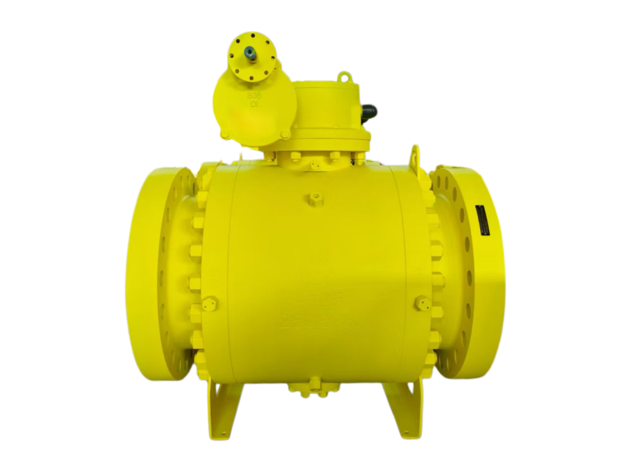
20″-600LB-RF 3-Piece Trunnion Ball Valve Forged
Description
20″ – 600LB – RF 3-Piece Forged Trunnion Ball Valve
Technical Data Sheet
1. General Information
| Item | Description |
|---|---|
| Valve Type | Trunnion Mounted Ball Valve |
| Nominal Size | 20 Inch (DN500) |
| Pressure Rating | Class 600 LB (PN100) |
| Body Construction | 3-Piece Body |
| Body Entry Type | Side Entry |
| Body Material | Forged Steel ASTM A105N (standard); A350 LF2 / A182 F316 optional |
| Flange Connection | RF (Raised Face) to ASME B16.5 Class 600 |
| Operation | Manual gear operator (standard); electric or pneumatic actuator (optional) |
| Application | Large bore, high pressure pipelines in oil, gas, chemical, and other demanding services requiring high reliability and tight shut-off |
2. Design & Manufacturing Standards
| Standard | Description |
|---|---|
| Design Code | API 6D / ASME B16.34 / ISO 14313 / BS 5351 |
| Body Construction | 3-piece, side entry, bolted, trunnion supported ball |
| Flange Dimensions | ASME B16.5 Class 600 RF |
| Face-to-Face Dimension | ASME B16.10 / API 6D (20″ Class 600 approx. 1194 mm) |
| Pressure-Temperature Rating | ASME B16.34 |
| Inspection & Testing | API 598 / API 6D |
| Fire Safe Design | API 607 / API 6FA (optional) |
| Low Emission Test | ISO 15848-1 (optional) |
| Anti-Static Device | API 6D / BS 5351 (standard) |
| Top Flange | ISO 5211 (for actuator mounting) |
3. Main Materials (Typical – can be customized)
| Component | Standard Material (Carbon Steel) | Optional Material (Low Temp / SS) |
|---|---|---|
| Body / Bonnet | Forged Steel ASTM A105N | ASTM A350 LF2 (low temp) / A182 F316 (SS) |
| Ball | A105 + ENP (Electroless Nickel Plating) | A182 F316 (SS) / F51 (Duplex) |
| Stem / Trunnion | A182 F6a (13Cr) or 17-4PH | A182 F316 / Inconel / Monel |
| Seat Support Ring | A105 + ENP | A182 F316 / F51 |
| Seat Sealing Material | Reinforced PTFE (RPTFE) | PEEK, Nylon, Metal hardfacing (Stellite) |
| Seat Spring | Inconel X-750 | 17-7PH Stainless Steel |
| Stem Bearing | PTFE + Stainless Steel | Self-lubricating composite |
| Packing | Flexible graphite / PTFE | Low emission packing (ISO 15848) |
| Gaskets | Flexible graphite + SS spiral wound | Metal ring gasket |
| Fasteners | Alloy Steel A193 B7 (zinc plated) | Stainless Steel A193 B8 |
Note: A105 and A105N are the same material; A105N is normalized.
4. Outline Dimensions & Weight
| Dimension Parameter | Value (Typical, API 6D) |
|---|---|
| Face-to-Face Length L | Approx. 1194 mm (47.0 inches) |
| Full Bore Diameter | Approx. 489 mm |
| Flange Outer Diameter D | Approx. 813 mm (32.0 inches) |
| Bolt Circle Diameter K | Approx. 724 mm |
| Flange Thickness C | Approx. 89 mm |
| Number / Diameter of Bolt Holes | 24 × 45 mm (1-5/8 inches) |
| Raised Face Diameter | Approx. 584 mm |
| Overall Height (with gear operator) H | Approx. 810 mm |
| Valve Weight (excluding actuator) | Approx. 3650 kg |
| Gear Operator Weight (reference) | Approx. 250 – 350 kg (depending on model) |
⚠ Dimensions above are typical references. Final dimensions to be confirmed with manufacturer’s drawing.
5. Pressure-Temperature Rating (ASME B16.34 – Carbon Steel Group 1.1)
| Temperature (°C) | Max. Working Pressure (bar) | Max. Working Pressure (psig) |
|---|---|---|
| -29 ~ 38 | 102.0 | 1480 |
| 100 | 97.9 | 1420 |
| 150 | 92.4 | 1340 |
| 200 | 86.9 | 1260 |
| 250 | 82.7 | 1200 |
| 300 | 71.7 | 1040 |
| 350 | 62.1 | 900 |
| 400 | 51.7 | 750 |
| 425 | 45.9 | 665 |
Data based on ASME B16.34 Material Group 1.1 (A105 / A216 WCB / A350 LF2). Maximum allowable working pressure decreases with increasing temperature. For stainless steel bodies (Group 2.1), pressure-temperature ratings differ.
6. Performance Data
| Parameter | Value |
|---|---|
| Pressure Rating | Class 600 (102 bar @ 38°C) |
| Shell Test Pressure (water) | 154 bar (approx. 2230 psig) |
| High-Pressure Seat Test (water) | 113 bar (approx. 1635 psig) |
| Low-Pressure Air Seat Test | 6 bar (approx. 87 psig) |
| Allowable Differential Pressure | Full rated pressure, bi-directional |
| Leakage Rate (soft seat) | Zero leakage (ISO 5208 Rate A / API 598 Rate A) |
| Leakage Rate (metal seat) | Class IV – V (API 598) |
| Temperature Range (RPTFE seat) | -29°C ~ +260°C |
| Temperature Range (PEEK seat) | -50°C ~ +315°C |
| Suitable Media | Water, oil, natural gas, chemical media, steam, etc. |
| Valve Type | 3-piece trunnion ball valve, full bore, bi-directional sealing, double block & bleed (DBB) |
| Automatic Cavity Pressure Relief | Standard (seat retraction relieves cavity pressure) |
| Blow-out Proof Stem | Standard |
| Anti-Static Device | Standard |
7. Key Design Features
-
Trunnion mounted ball – Ball is supported by upper and lower stem bearings; line pressure forces are absorbed by the trunnion bearings, ensuring low operating torque and stable sealing performance, especially for large bore and high pressure applications.
-
3-piece side entry body – Bolted 3-piece construction allows inline maintenance without removing the valve from the pipeline.
-
Double block & bleed (DBB) – Upstream and downstream independent seat sealing provides bi-directional shut-off with zero leakage; installation is non-directional.
-
Spring-energized seats – Pre-loaded springs maintain seat-to-ball contact even at low pressure, ensuring reliable sealing.
-
Automatic cavity pressure relief – When the valve is in the fully open or fully closed position, excess pressure trapped in the body cavity can be relieved by seat retraction, protecting the valve.
-
Fire safe design (optional) – If the non-metallic seat is softened or destroyed by fire, the metal sealing surface of the seat support ring contacts the ball to provide secondary metal-to-metal sealing, compliant with API 607 or API 6FA. (API 607 6th Edition now covers the scope formerly addressed by API 6FA.)
-
Blow-out proof stem – Stem is designed with anti-blowout retention, ensuring it cannot be accidentally ejected under pressure.
-
Anti-static device – A spring-loaded anti-static device provides electrical continuity between the ball, stem, and body, preventing static charge accumulation.
-
Emergency sealant injection – Sealant injection fittings are provided on the stem and seat areas; sealant can be injected to temporarily stop leakage in an emergency.
-
Full bore design – The valve bore matches the pipeline internal diameter, allowing pipeline pigging with minimal flow resistance.
8. Actuation Options
| Actuation Type | Remarks |
|---|---|
| Manual gear operator | Standard configuration, with position indicator and mechanical stop |
| Electric actuator | On-off or modulating (4-20mA); direct mounting on ISO 5211 top flange |
| Pneumatic actuator | Double-acting or spring-return; with solenoid valve and limit switches |
| Hydraulic / Gas-over-oil actuator | For emergency shut-down on long-distance pipelines |
9. Ordering Information
Please provide the following when ordering:
-
Valve size (20″), pressure rating (Class 600)
-
Body material (A105 / A350 LF2 / F316) and NACE MR0175 requirement
-
Seat material (RPTFE / PEEK / metal seated)
-
Flange standard and facing (RF / RTJ)
-
Media name, temperature, and pressure
-
Actuation type (gear operator / electric / pneumatic)
-
Special requirements (fire-safe API 607, anti-static, low emission packing ISO 15848, etc.)
-
Third-party inspection requirement (BV, DNV, TÜV, etc.)


