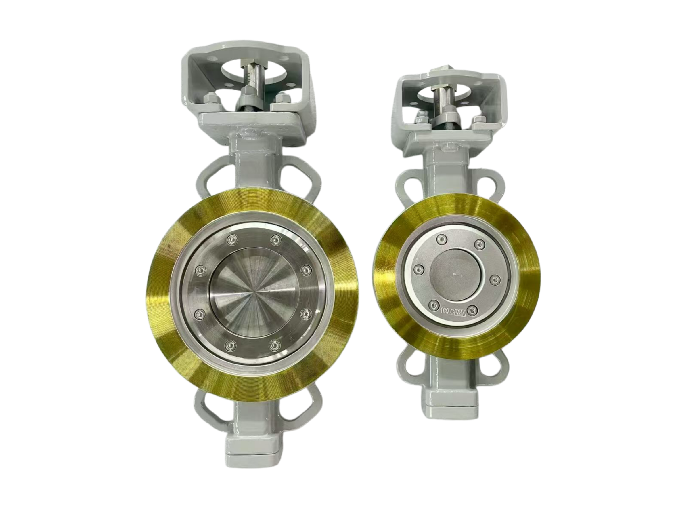
Wafer Type Triple Offset Butterfly Valve – Multi‑Drilled Holes
Description
Wafer Type Triple Offset Butterfly Valve – Multi‑Drilled Holes
Technical Data Sheet
1. Product Overview
This wafer type triple offset butterfly valve features a multi‑drilled hole design on the valve body. Instead of conventional through‑bolts or lugged holes, the body is provided with multiple drilled and optionally tapped holes (e.g., threaded blind holes or through holes) arranged circumferentially. This allows flexible mounting using bolts or studs directly into the valve body, simplifying installation, improving centering accuracy, and enabling secure fixing between pipe flanges without separate nuts or alignment rings.
The triple offset (TOV) metal‑to‑metal sealing technology ensures bi‑directional zero leakage, low torque, long cycle life, and suitability for demanding services (high temperature, high pressure, corrosive or abrasive media).
2. Key Design Feature – Multi‑Drilled Holes
| Feature | Description |
|---|---|
| Hole configuration | Multiple drilled holes evenly spaced on the wafer body outer diameter |
| Hole type | Through holes or threaded blind holes (e.g., metric or UNC threads) |
| Purpose | – Direct bolting to pipe flanges without nuts – Precise centering between flanges – Eliminates need for separate alignment rings or clamps – Allows easy removal and re‑installation |
| Standard pattern | Customised to customer flange drilling templates (e.g., ASME B16.5, EN 1092, JIS, or special) |
| Material compatibility | Holes are drilled after body heat treatment; edges chamfered to avoid gasket damage |
Benefit: The multi‑drilled hole design simplifies on‑site assembly, reduces fastener inventory, and ensures repeatable alignment, especially in large diameter or high vibration applications.
3. Triple Offset Principle (Summary)
| Offset | Effect |
|---|---|
| 1st (shaft to seat centre) | Immediate disc lift-off |
| 2nd (shaft to pipe centre) | Reduced friction |
| 3rd (cone axis offset) | Cam‑action sealing, no rubbing |
Result: Zero leakage (API 598 Rate A), bi‑directional, virtually frictionless operation, long seal life.
4. Main Technical Parameters
| Parameter | Specification |
|---|---|
| Product type | Wafer type triple offset butterfly valve |
| Body pattern | Wafer (fits between ASME / EN flanges) |
| Hole feature | Multi‑drilled holes – through or threaded (as specified) |
| Size range | DN50 – DN1200 (2″ – 48″); larger on request |
| Pressure rating | ASME Class 150 / 300 / 600; PN10 – PN64 (up to PN100 on request) |
| Temperature range | -29°C up to +650°C (depending on materials) |
| Media | Water, steam, oil, gas, chemical fluids, high‑temp fluids, cryogenic (down to -196°C with special trim) |
| Leakage rating | API 598 Rate A / ISO 5208 Rate A – zero leakage |
| Fire safe | API 607 / API 6FA |
| Face‑to‑face length | API 609 Category B (short pattern) |
| Top flange | ISO 5211 for direct actuator mounting (without bracket, ready for actuator) |
5. Multi‑Drilled Holes – Detailed Specifications
| Parameter | Options |
|---|---|
| Hole diameter | According to mating flange bolt size (e.g., Ø18, Ø22, Ø26 mm, or ¾″, ⅞″, 1″ UNC) |
| Hole type | – Through hole (clearance hole) – Threaded hole (e.g., M16, M20, M24, or ⅝″‑11 UNC, ¾″‑10 UNC) |
| Thread depth | For blind holes: 1.5× nominal diameter or full body thickness (if thickness allows) |
| Number of holes | Matches flange bolt count (4, 8, 12, 16, 20, etc.) |
| Hole circle diameter | Per ASME B16.5 / EN 1092 / customer drawing |
| Edge finish | Chamfered or countersunk to protect gasket |
| Bolt / stud material | Supplied by customer; recommended: high‑temperature alloy steel or stainless steel |
Note: For threaded holes, the valve body thickness must be sufficient to provide full thread engagement. For through holes, nuts are required on the opposite side (standard wafer practice) – but multi‑drilled through holes allow bolting from either side.
6. Materials of Construction (Standard & High Temp)
| Component | Standard Material (≤400°C) | High Temp Material (≤650°C) | Low Temp / Corrosion |
|---|---|---|---|
| Body | WCB cast steel | WC6, WC9, C12A, SS310H | CF8M (SS316), Duplex |
| Disc | SS304 + Stellite hardface | Inconel 718 + Stellite | CF8M, Duplex, Hastelloy |
| Seat hardfacing | Stellite 6 (cobalt alloy) | Stellite 6 or 21 | Stellite or alloy 625 |
| Stem | 17‑4PH (H1150) | Inconel 718, Nimonic 90 | SS316, Monel K500 |
| Packing | Flexible graphite (low emission) | Flexible graphite + anti‑extrusion rings | PTFE / graphite |
| Bearings | High‑temp bronze | Graphite‑impregnated nickel alloy | PTFE‑composite |
| Body holes | Drilled after heat treatment | Same | Same |
7. Actuator Interface – Ready for Actuator
| Feature | Specification |
|---|---|
| Top flange | ISO 5211 (F05, F07, F10, F12, F14, F16, F25 according to valve size) |
| Drive connection | Square or keyed drive per ISO 5211 |
| Actuator mounting | Direct – no bracket required (optional bracket available for non‑ISO actuators) |
| Actuator types | Pneumatic (double acting / spring return), electric, hydraulic (customer supplied) |
| Handwheel override | Optional (declutchable type, side‑mounted or top‑mounted) |
| Valve position indicator | Visual indicator on top flange; optional limit switch / positioner mounting |
8. Face‑to‑Face Dimensions (Wafer, API 609 Cat. B)
| DN | NPS | L (mm) |
|---|---|---|
| 50 | 2″ | 108 |
| 80 | 3″ | 114 |
| 100 | 4″ | 127 |
| 150 | 6″ | 140 |
| 200 | 8″ | 152 |
| 250 | 10″ | 165 |
| 300 | 12″ | 178 |
| 350 | 14″ | 190 |
| 400 | 16″ | 216 |
| 500 | 20″ | 229 |
| 600 | 24″ | 267 |
For Class 300 / 600 or higher pressure, face‑to‑face dimensions may increase – consult factory.
9. Multi‑Drilled Hole Pattern – Typical Example (Class 150, DN150)
| Parameter | Value |
|---|---|
| Hole circle diameter | 240 mm (per ASME B16.5 for 6″ 150#) |
| Number of holes | 8 |
| Hole diameter | Ø22 mm (clearance) or M20 threaded |
| Hole type | Through hole (standard) or threaded blind hole |
| Body thickness at hole location | ≥ 20 mm |
Custom patterns available per customer flange drilling template or drawing.
10. Applicable Standards
| Category | Standard |
|---|---|
| Design | API 609 Category B, ASME B16.34, ISO 10631, EN 593 |
| Face‑to‑face | API 609, ASME B16.10, ISO 5752 |
| Flange connection (wafer) | ASME B16.5, ASME B16.47, EN 1092 (the wafer body fits between these flanges) |
| Hole drilling pattern | Per customer specification or standard flange drilling template |
| Testing | API 598, ISO 5208, EN 12266 |
| Fire safety | API 607, API 6FA |
| Actuator mounting | ISO 5211 |
11. Testing & Inspection
| Test | Pressure / Condition | Acceptance |
|---|---|---|
| Shell (hydrostatic) | 1.5 × pressure rating | No leakage, no visible deformation |
| High‑pressure seat | 1.1 × pressure rating | Zero leakage (API 598 Rate A) |
| Low‑pressure air seat | 0.6 MPa | Zero bubbles |
| Optional high‑temperature test | At customer request | Torque & sealing at operating T° |
| PMI (Positive Material Identification) | On request | Confirms alloy composition |
| NDE (PT, RT) | Per ASME B16.34 | As specified |
12. Typical Applications
-
Chemical & petrochemical plants
-
Refineries (high temp & corrosive services)
-
Power generation (steam, cooling water, flue gas)
-
Pulp & paper (liquors, steam)
-
HVAC & district heating (high temperature water)
-
Offshore & marine (where space and weight are critical)
-
Industrial process lines requiring easy disassembly
13. Ordering Information
Please supply the following for correct selection:
-
Valve size (DN / NPS) and pressure class
-
Multi‑drilled hole details:
-
Through hole or threaded blind hole?
-
Thread size (if threaded) – e.g., M20, ¾″‑10 UNC
-
Number of holes and hole circle diameter (or reference flange standard)
-
-
Operating temperature, pressure, and medium
-
Body / disc / seat material
-
Actuator type (if to be supplied by customer, or just ISO 5211 pad prepared)
-
Any special testing or certification (NACE, low fugitive emission, etc.)
Important: The multi‑drilled hole design is a custom feature. The valve body is drilled after final heat treatment to maintain dimensional accuracy and material integrity. Please provide the mating flange bolt circle drawing or standard (ASME, EN, JIS) to ensure correct hole alignment.


