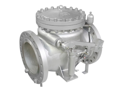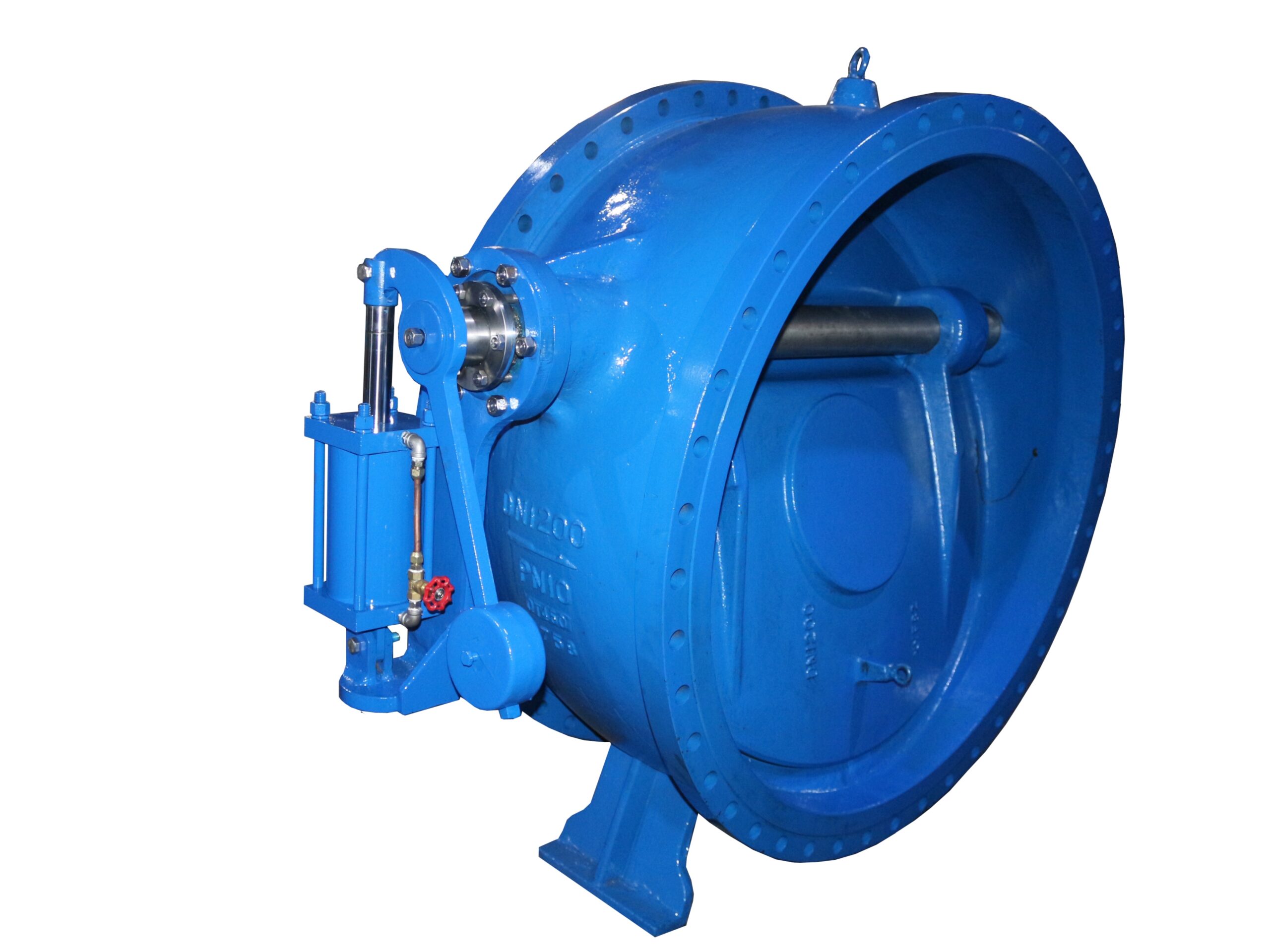
Hydraulic Dashpot Butterfly Check Valve
Description
Hydraulic Dashpot Butterfly Check Valve
Technical Data Sheet
1. Product Overview
The Hydraulic Dashpot Butterfly Check Valve is an automatic valve installed at the discharge outlet of pumps in industrial water supply, wastewater treatment plants, and similar systems. It opens and closes automatically by the pressure of the medium in the pipeline. The valve is equipped with a hydraulic dashpot device that is completely isolated from the medium. The closing process consists of two stages – fast close and slow close – which effectively prevent destructive water hammer and protect the pump and piping system.
2. Model Designations
Common model series include:
| Model Series | Description |
|---|---|
| H47X / H47H | Butterfly buffer check valve |
| HH47X / HH47H | Micro-resistance slow-closing butterfly check valve |
| H47XF | Butterfly buffer check valve (FKM rubber seal) |
| HDH47X | Butterfly buffer check valve |
| DHh47X | Butterfly slow-closing check valve |
3. Main Technical Parameters
3.1 Pressure and Size Ratings
| Parameter | Range |
|---|---|
| Nominal Diameter DN (mm) | 50 ~ 2400 |
| Nominal Pressure PN (MPa) | 0.25 ~ 2.5 |
| Shell Test Pressure (MPa) | 1.5 × PN |
| Seal Test Pressure (MPa) | 1.1 × PN |
| Working Pressure (MPa) | Equal to PN |
| Maximum Working Temperature (°C) | ≤80 (standard) / ≤200 (special) |
| Applicable Temperature Range (°C) | –20 ~ +80 |
3.2 Pressure Class Details
| Nominal Pressure PN (MPa) | Shell Test (MPa) | Seal Test (MPa) |
|---|---|---|
| 1.0 | 1.5 | 1.1 |
| 1.6 | 2.4 | 1.76 |
| 2.5 | 3.75 | 2.75 |
3.3 Slow‑Closing Time
| Parameter | Specification |
|---|---|
| Slow‑closing time | 3 ~ 60 seconds (adjustable) |
4. Main Parts Materials
4.1 Standard Configuration
| Part Name | Material |
|---|---|
| Body | Ductile iron (QT450‑10) / Grey cast iron / Cast steel |
| Disc | Ductile iron / Grey cast iron / Cast steel |
| Disc sealing ring | NBR / EPDM |
| Disc retaining ring | Ductile iron / Carbon steel |
| Shaft | Stainless steel (20Cr13) |
| Bearing | Copper‑based composite / Self‑lubricating material |
| Packing | PTFE / NBR |
| Packing gland | HPb58‑2 |
| Seal pressure ring | Q235A |
| Counterweight | HT200 |
4.2 Metal‑Seal Option (High‑Temperature Service)
| Part Name | Material |
|---|---|
| Body sealing face | Stainless steel |
| Disc sealing face | Bronze |
5. Main Overall Dimensions
5.1 HH47X / H47X / H47H Series – Dimensions (mm)
| DN | L | H | B1 | B2 |
|---|---|---|---|---|
| 200 | 230 | 550 | 540 | 600 |
| 250 | 250 | 630 | 600 | 700 |
| 300 | 270 | 690 | 650 | 740 |
| 350 | 290 | 780 | 710 | 800 |
| 400 | 310 | 860 | 770 | 870 |
| 450 | 330 | 910 | 830 | 920 |
| 500 | 350 | 980 | 900 | 1000 |
| 600 | 390 | 1070 | 1090 | 1250 |
| 700 | 430 | 1220 | 1200 | 1360 |
| 800 | 470 | 1320 | 1320 | 1480 |
| 900 | 510 | 1430 | 1420 | 1580 |
| 1000 | 550 | 1550 | 1550 | 1700 |
| 1200 | 630 | 1800 | 1780 | 1950 |
| 1400 | 710 | 1980 | 2000 | 2175 |
5.2 DHh47X‑10Q Flange Connection Dimensions (mm)
| DN | D | D1 | D2 | L | b | f | n‑d |
|---|---|---|---|---|---|---|---|
| 300 | 445 | 400 | 370 | 270 | 24.5 | 4 | 12‑Φ23 |
| 350 | 505 | 460 | 429 | 290 | 24.5 | 4 | 16‑Φ23 |
| 400 | 565 | 515 | 480 | 310 | 24.5 | 4 | 16‑Φ28 |
| 450 | 615 | 585 | 530 | 330 | 25.5 | 4 | 20‑Φ28 |
| 500 | 670 | 620 | 582 | 350 | 26.5 | 4 | 20‑Φ28 |
| 600 | 780 | 725 | 682 | 390 | 30.0 | 5 | 20‑Φ31 |
6. Working Principle
6.1 Opening Process
The valve opens automatically by the forward flow pressure of the medium. The disc features a large‑eccentric design, which generates a high opening torque even under low water pressure, allowing the valve to open with minimal flow resistance and significant energy savings.
6.2 Closing Process (Two‑stage)
| Stage | Angle Range | Characteristics |
|---|---|---|
| Fast‑close | approx. 75° → 30° | Dashpot exerts minimal resistance; disc closes rapidly |
| Slow‑close | approx. 30° → 0° | Dashpot damping increases; disc slows down to avoid sealing face impact |
Two‑stage damping action:
Primary damping allows relatively fast rotation; when the disc approaches the closed position (about 5° before fully closed), secondary damping engages, reducing the disc speed to prevent impact on the sealing surfaces, thus extending service life.
6.3 Adjustment
-
The fast‑close and slow‑close strokes and speeds can be adjusted via the corresponding stroke adjustment screws.
-
Turning the adjustment screw clockwise shortens the travel, resulting in a shorter fast‑close phase and a longer slow‑close phase.
-
Adjustment can also be made by changing the position of the counterweight on the lever arm or by adjusting the throttle plug.
7. Product Features
| Feature | Description |
|---|---|
| Compact structure | Small footprint, short face‑to‑face dimension, light weight |
| Low flow resistance | Large‑eccentric butterfly design reduces pressure drop, energy‑efficient |
| Two‑stage slow closure | Fast + slow closing effectively eliminates water hammer |
| Reliable sealing | Soft seal gives zero leakage; metal seal available for high temperature |
| Smooth operation | Stable opening/closing, no vibration, no noise |
| Highly adjustable | Fast/slow strokes and speeds can be tuned over a wide range |
| Dashpot isolated | Hydraulic damping unit is completely separated from the medium, unaffected by fluid properties |
| Flexible installation | Can be installed horizontally or vertically |
8. Applicable Standards
| Standard | Title |
|---|---|
| CJ/T282‑2008 | Butterfly slow‑closing check valves |
| GB/T 17241.6‑2008 | Integral cast iron pipe flanges |
| GB/T 9113‑2010 | Integral steel pipe flanges |
| GB/T 12221‑2005 | Face‑to‑face dimensions of metal valves with flanged ends |
| GB/T 13927‑2008 | Pressure testing of industrial valves |
| JB/T 78‑94 | Flange connection dimensions |
Flange connections can also be supplied to ISO (standard) or other international standards upon request.
9. Applicable Media & Service Conditions
| Item | Specification |
|---|---|
| Applicable media | Water, seawater, sewage, oil, weak corrosive fluids |
| Temperature range | ≤80°C (standard) / ≤200°C (special) / ≤350°C (metal‑seal high‑temperature version) |
| Typical applications | Power generation, mining, petroleum, chemical, thermal gas, metallurgy, wastewater treatment, municipal construction, food, pharmaceutical, papermaking, textile, water supply & drainage, etc. |
| Typical installation | Pump discharge outlet, blower discharge outlet |
Note: The technical data above are reference values based on general industry standards. For final selection, please consult the official product catalog of the specific manufacturer. For special service conditions (high temperature, high pressure, aggressive media), contact the supplier for customised solutions.