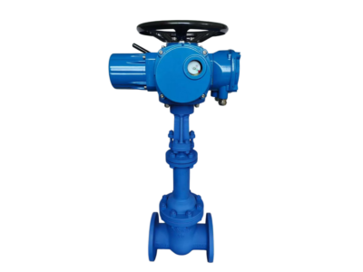
24″-600LB-RF Control Valve Type Globe Balance Caged
Description
Valve Type: Globe Style, Balanced, Cage-Guided
Actuator Type: Electro-Hydraulic, Modulating, Explosion-Proof
Assembly Model: 24″-600LB-RF / 480V Electro-Hydraulic Actuator
1. General Description
Complete control valve assembly consisting of a 24″ Class 600 globe balanced caged control valve with raised face flanges, and an integrated electro-hydraulic linear actuator. The actuator is designed for continuous modulating service, explosion-proof certified, and operates on 480V 3-phase power. The assembly is suitable for high pressure drop, high flow, and hazardous area applications (oil & gas, petrochemical, power generation).
2. Valve Specifications
| Parameter | Value |
|---|---|
| Nominal Size | 24″ (DN 600) |
| Pressure Rating | Class 600 (PN 100) |
| End Connections | Raised Face (RF) per ASME B16.5 |
| Valve Type | Globe, Balanced, Cage-Guided |
| Bonnet Type | Standard / Extension / Bellows Seal (optional) |
| Packing | PTFE V-ring / Graphite (low emission optional) |
| Gasket | Spiral wound (316 SS + Graphite) |
| Flow Direction | Flow-to-open (standard), flow-to-close (optional) |
| Shut-off Class | ANSI/FCI 70‑2 Class IV (standard); Class V / VI optional |
| Seat Leakage | ≤ 0.01% of Cv for Class IV |
3. Valve Materials of Construction (Standard)
| Component | Material |
|---|---|
| Body / Bonnet | WCB (A216 Gr. WCB) / LCB / CF8M (optional) |
| Cage | 17‑4 PH SS / 316 SS |
| Plug (Balanced) | 316 SS with Stellite® hardfacing |
| Seat Ring | 316 SS + Stellite® |
| Stem | 17‑4 PH SS / Inconel® |
| Guide Bushings | 316 SS / reinforced PTFE |
Other alloys (Hastelloy®, Monel®, Duplex) available on request.
4. Valve Performance Data
| Parameter | Value |
|---|---|
| Seat Diameter | Full bore (reduced trim optional) |
| Flow Characteristic | Equal percentage (standard), Linear / Quick-opening (optional) |
| Rangeability | 50:1 (equal percentage / linear) |
| Cv (full open) | Approx. 6,500 – 7,200 (depending on trim) |
| Stroke | 4″ (100 mm) |
| Maximum Pressure Drop | Up to 600 psi (limited by actuator and trim) |
| Temperature Range (WCB body) | -29°C to +425°C |
| Temperature Range (special materials) | Cryogenic to +650°C (consult factory) |
5. Electro-Hydraulic Actuator Specifications
| Parameter | Value |
|---|---|
| Actuator Type | Electro-Hydraulic, Linear, Self-contained |
| Stroke | 4″ (100 mm) – matches valve stroke |
| Control Mode | Continuous modulating |
| Fail-Safe Action | Fail-Open / Fail-Close / Fail-Last (configurable) |
| Manual Override | Handwheel (standard) or hydraulic hand pump (optional) |
| Duty Cycle | 100% modulating duty |
6. Power & Control Data (Actuator)
| Parameter | Value |
|---|---|
| Supply Voltage | 480VAC, 3-Phase, 50/60 Hz |
| Control Signal | 4-20 mA (standard), 0-10 VDC, HART, Profibus, Modbus, Foundation Fieldbus |
| Feedback Signal | 4-20 mA (isolated) |
| Resolution | <0.25% (standard); up to 0.1-0.2% (high precision) |
| Deadband | Adjustable 0.2% – 5% |
| Linearity | ±0.2% (typical) |
| Hysteresis | <0.5% |
7. Actuator Performance Data
| Parameter | Value |
|---|---|
| Output Thrust (linear) | Up to 400 kN (90,000 lbf) – sized per valve requirement |
| Modulating Speed | Adjustable (customer specified) |
| Response Time | <0.4 sec (typical) |
| Positioning Accuracy | ±0.2% of full stroke (standard); ±0.05% (high precision) |
| Operating Frequency | Up to 5 Hz (servo-driven models) |
| Hydraulic Operating Pressure | 100 – 160 bar (standard); up to 210 bar max |
| Hydraulic Oil | ISO VG 15 / 32# |
8. Hazardous Area & Environmental Ratings (Actuator)
| Parameter | Value |
|---|---|
| Explosion-Proof Certification | ATEX / IECEx Ex db IIB T4 Gb or Ex db IIC T4 Gb; CSA/FM Class I Div 1 & 2; China Ex d IIB T4 / Ex d IIC T6 Gb (optional) |
| Enclosure Protection | IP66 / IP67 / NEMA 4X (explosion-proof enclosure) |
| Ambient Temperature Range | Standard: -20°C to +70°C; Low-temp option: -46°C; High-temp option: up to +120°C (custom) |
| Relative Humidity | 45 – 85% (explosion-proof models) |
| Suitable Environment | Flammable gases, vapors, dust (Zone 1 & 2, Class I Div 1 & 2) |
9. Actuator Features & Functions
| Feature | Description |
|---|---|
| Continuous Modulating Control | Precision valve positioning via 4-20 mA signal |
| Fail-Safe Action | Spring-return or accumulator-based (fail-open/close/last) |
| Partial Stroke Testing (PST) | Configurable for ESD/SIL applications |
| ESD/PSD Inputs | Single or dual ESD inputs with solenoid options |
| Data Logging | Up to 3,000 events (position, alarms, diagnostics) |
| Position Feedback | Independent limit switches + 4-20 mA transmitter |
| Local Control | LCD display with push-button or IR remote programming |
| Non-Intrusive Setup | Parameter configuration without opening enclosure |
| Overload Protection | Stall, over-torque, phase loss, temperature protection |
| Manual Override | Handwheel or hydraulic hand pump |
| Valve Jam Detection | Timed alarm on incomplete stroke |
| Network Protocols | HART, Profibus DP/PA, Modbus RTU/TCP, Foundation Fieldbus |
10. Hydraulic System Data (Actuator)
| Parameter | Value |
|---|---|
| Pump Type | High-performance gear pump (international brand) |
| Motor Type | AC induction / Servo motor (high-precision models) |
| Accumulator | Optional for fail-safe and power outage operation |
| Hydraulic Valves | Solenoid valve, relief valve, flow control valve |
| Reservoir Capacity | 800 – 2,500 cc (size dependent) |
| Flow Rate | 0.38 – 9.0 L/min (configurable) |
| Filtration | Suction strainer + return filter |
| Sealing | Zero-leak design |
11. Valve & Actuator Dimensions (Approximate)
| Component | Value |
|---|---|
| Valve face-to-face (ASME B16.10, Class 600) | 42″ (1067 mm) |
| Valve height (CL to bonnet top) | ~72″ (1830 mm) – without actuator |
| Actuator height (from valve CL) | 600 – 1000 mm (23 – 40 in) |
| Actuator width | 300 – 500 mm (12 – 20 in) |
| Actuator depth | 250 – 400 mm (10 – 16 in) |
| Valve weight (body only) | ~1,850 lb (840 kg) |
| Actuator weight | 150 – 400 kg (330 – 880 lb) |
12. Compliance & Standards
| Item | Standard |
|---|---|
| Valve design | ASME B16.34, IEC 60534 |
| Valve face-to-face | ASME B16.10 |
| Flange dimensions | ASME B16.5 |
| Valve testing | API 598 / IEC 60534‑4 |
| Actuator mounting interface | ISO 5210, MSS SP-101 |
| Actuator explosion protection | ATEX, IECEx, CSA, FM, CCC Ex |
| Actuator functional safety | IEC 61508 (SIL 2 / SIL 3 capable) |
| Actuator EMC | IEC 61000 series |
| Actuator enclosure | IEC 60529 (IP66/IP67) |
| Actuator testing | EN 15714‑4:2009 |
| Quality system | ISO 9001 |
13. Ordering Information
Please specify the following when ordering the complete assembly:
| Item | Options |
|---|---|
| Valve size / rating | 24″ – Class 600 RF |
| Valve body / trim material | WCB/316SS, or others |
| Flow characteristic | Equal % / Linear / Quick-opening |
| Required Cv | ______ |
| Shut-off class | IV / V / VI |
| Actuator fail-safe action | Fail-open / Fail-close / Fail-last |
| Actuator output thrust | Sized to valve |
| Modulating speed (full stroke time) | ______ seconds |
| Control signal | 4-20 mA / HART / Profibus / Modbus / Foundation Fieldbus |
| Precision class | Standard (<0.25%) / High (<0.1%) |
| Explosion-proof certification | ATEX / IECEx / CSA / FM / CCC Ex (specify zone/division) |
| Ambient temperature range | ______ °C |
| Manual override | Handwheel / Hydraulic hand pump |
| Additional accessories | Accumulator, PST module, limit switches, solenoid valve |
| Special requirements | Low emission packing, extended bonnet, bellows seal, high-temperature hydraulic oil, etc. |
14. Notes
-
All data are nominal and subject to final engineering selection based on process conditions.
-
The assembly is fully tested prior to shipment per applicable standards.
-
For SIL 2 / SIL 3 applications, a safety manual and FMEDA data are available upon request.
-
Explosion-proof certifications must be confirmed for the specific hazardous area classification.
-
Valve and actuator are matched for stroke, thrust, mounting, and control compatibility.