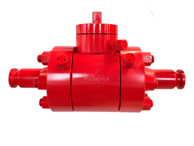
API 10000# Motorised Adjustable Choke Valve
Description
Electric Actuated Angle Pattern Throttling Valve Technical Data Sheet
(API 6A Standard / Electric Actuated)
1. Product Overview
| Item | Description |
|---|---|
| Product Type | Electric Actuated Angle Pattern Throttling Valve / Electric Choke Valve |
| Design Standard | API 6A (Specification for Wellhead and Christmas Tree Equipment) |
| Valve Body Type | Angle Pattern (90°) |
| Operation | Electric Actuator (with manual override handwheel) |
| Connection Type | Flanged (6B / 6BX) with RTJ Groove |
| Nominal Size | 1 13/16″ ~ 4 1/16″ (46mm ~ 103mm) |
| Pressure Rating | API 2000 psi ~ API 10000 psi (13.8 MPa ~ 103.5 MPa) |
| Material Class | AA ~ FF (per NACE MR0175 / ISO 15156) |
| Temperature Class | K, L, P, R, S, T, U, V (per API 6A) |
| Product Specification Level (PSL) | PSL 1 ~ PSL 4 (as required) |
| Performance Requirement | PR1 ~ PR2 |
| Trim Type | Needle & Seat / Plug & Seat (Hardfaced with Stellite or Tungsten Carbide) |
2. Applicable Standards & Specifications
| Item | Standard |
|---|---|
| Design & Manufacturing | API 6A (20th Edition or Latest) |
| Flange End Dimensions | API 6A (6B / 6BX Flanges) with RTJ Groove |
| Pressure-Temperature Rating | API 6A Annex F |
| Material Requirements | NACE MR0175 / ISO 15156 (for sour service) |
| Testing & Inspection | API 6A Annex F / API 6A Clause 10 |
| RTJ Gaskets | API 6A / ASME B16.20 |
| Electric Actuator Standard | IEEE/ISO 12100 / IEC 60034 / NEMA / IECEx / ATEX (as specified) |
| Quality Management | API Q1 / ISO 9001 |
3. Main Technical Parameters
| Item | Parameter Range / Description | |||
|---|---|---|---|---|
| Pressure Rating (API) | 2000 psi | 3000 psi | 5000 psi | 10000 psi |
| Nominal Sizes (in/mm) | 1 13/16″ (46) – 4 1/16″ (103) | |||
| Shell Test Pressure | 1.5 x Rated Working Pressure (per API 6A) | |||
| Seat Test Pressure | 1.1 x Rated Working Pressure (per API 6A) | |||
| Applicable Media | Crude Oil, Natural Gas, Drilling Mud, Fracturing Fluids, Water Injection, CO2, H2S, etc. | |||
| Working Temperature | Per API 6A Temperature Classes: -60°C ~ 180°C+ (depending on class) | |||
| Material Class (NACE) | AA (General), BB (General), CC (Sour), DD (Sour), EE (Sour), FF (Sour) | |||
| Flow Direction | Flow tends to close (Flow under seat – recommended for throttling) | |||
| Leakage Rate | API 6A PR2 (Zero detectable leakage) | |||
| Choke Trim Type | Needle & Seat / Plug & Seat (Hardfaced) | |||
| Orifice Sizes (Fixed Choke) | Φ3 ~ Φ12 mm (for fixed choke version) |
4. Electric Actuator Specifications
| Item | Specification |
|---|---|
| Actuator Type | Multi-turn electric actuator / Part-turn electric actuator (with thrust base) |
| Power Supply | 220V AC / 380V AC / 415V AC / 24V DC (as specified), 50/60 Hz |
| Control Mode | Modulating / Regulating type (4-20mA analog signal for position control) |
| Position Feedback | 4-20mA DC (output signal) |
| Manual Override | Handwheel for emergency manual operation |
| Protection Class | IP67 / IP68 (standard); IP68 (optional for subsea) |
| Explosion Proof Class | Ex d IIB T4 / Ex d IIC T4 (for hazardous areas) |
| Motor Duty | S2 – 15 min / S4 – 25% (intermittent) |
| Ambient Temperature | -20°C ~ +60°C (standard); -40°C ~ +60°C (low temp option) |
| Position Indicator | Continuous position indicator (local and remote) |
| Torque Limiter | Adjustable torque limiter for overload protection |
| Heater / Thermostat | Built-in anti-condensation heater (standard) |
| Cable Entries | 2 x PF3/4″ or NPT 3/4″ (as specified) |
| Control Options | – On-Off control – Modulating control (4-20mA) – Profibus / Modbus / Foundation Fieldbus (optional) |
| Fail-Safe Mode | Fail-last-position / Fail-close / Fail-open (with optional battery backup or spring-return unit) |
5. Material of Construction (API 6A Material Classes)
Materials selected per API 6A based on service conditions (H2S, CO2, Temperature).
| Part Name | Material Class AA/BB (General Service) | Material Class DD/EE/FF (Sour Service) |
|---|---|---|
| Body | AISI 4130 / AISI 4140 (Low Alloy Steel) / A216 WCB | 316 Stainless Steel / F51 Duplex / Inconel 718 / F55 Super Duplex |
| Bonnet / Cover | AISI 4130 / AISI 4140 (Low Alloy Steel) / A105 | 316 Stainless Steel / F51 Duplex / Inconel 718 |
| Stem / Needle | 17-4 PH / Inconel 718 + Hardfacing (Stellite) | Inconel 625 / 718 + Hardfacing (Stellite) |
| Seat | Integral / Inconel Clad + Stellite / Tungsten Carbide | Inconel Clad + Stellite / Tungsten Carbide |
| Choke Trim (Disc/Plug) | Stellite 6 / 21 / Tungsten Carbide | Stellite 6 / 21 / Tungsten Carbide |
| Packing / Seals | PTFE / Flexible Graphite / HNBR / Viton (per temperature) | |
| Body Gasket | API 6A Ring Gasket (R, RX, BX types) – Soft Iron / 316L / Inconel | |
| Bonnet Bolting | A193 B7 / A194 2H | A193 B7M / A194 2HM / Inconel 718 |
| Yoke / Actuator Mount | Carbon Steel (Epoxy coated) / Stainless Steel | |
| Electric Actuator Housing | HT200 Gray Iron / WCB / Aluminum Alloy (coated) |
6. Structural Features & Working Principle
6.1 Valve Design Features
| Feature | Description |
|---|---|
| API 6A Compliant Design | Designed, manufactured, and tested in full compliance with API 6A specification, ensuring reliability in critical wellhead and flowline applications . |
| Angle Pattern Configuration | 90-degree angle body design minimizes fluid turbulence and erosion caused by high-velocity, solids-laden fluids common in oil and gas production . |
| Precise Throttling / Choking Function | The valve uses a tapered needle or plug that moves linearly into a mating seat. By rotating the stem, the flow area is precisely controlled, managing downstream pressure and flow rate . |
| Severe Service Trim | Critical sealing and throttling surfaces are overlaid with Stellite or fitted with Tungsten Carbide inserts. These materials provide exceptional resistance to erosion from sand, proppant, and high-velocity flow . |
| RTJ Flanged Connections | API 6A standard 6B or 6BX flanges with Ring-Type Joint grooves ensure reliable metal-to-metal seal capable of containing extreme wellhead pressures. |
| Position Indication | Continuous position indication on actuator and remote 4-20mA feedback signal. Optional local mechanical indicator on valve . |
| Fixed or Adjustable Trim | Available as adjustable (needle/plug) for continuous modulation or fixed (interchangeable orifice) for constant choke . |
| Quick Disassembly (Optional) | Some designs feature union nut connection (hammer union) between body and bonnet for rapid trim inspection/replacement . |
6.2 Working Principle
-
Modulating Control: The electric actuator receives a 4-20mA control signal from the control system (DCS/PLC), positioning the stem and plug precisely.
-
Flow Regulation: As the plug moves into the seat, the annular flow area is reduced, creating pressure drop and controlling flow rate.
-
Erosion Resistance: Hardfaced trim ensures long service life even with abrasive media (sand, proppant).
-
Fail-Safe Options: Available with battery backup or spring-return for fail-safe positioning on power loss.
7. Choke Trim Options
| Trim Type | Application | Description |
|---|---|---|
| Stellite Overlay | General purpose throttling, moderate sand | Hard alloy overlay (Stellite 6/21) on 17-4PH or Inconel substrate |
| Tungsten Carbide (Solid) | Severe erosive service (high sand, fracturing) | Solid tungsten carbide seat and plug for maximum erosion resistance |
| Tungsten Carbide (Coated) | High velocity, erosive media | HVOF or PVD coated trim for enhanced wear resistance |
| Ceramic Trim | Extreme erosion / corrosion | High-purity ceramic components for longest service life in abrasive fluids |
8. Dimensional Data (Reference – API 6A 5000 psi / 10000 psi)
Note: Dimensions are for reference only. Final dimensions vary by manufacturer, PSL level, actuator size, and specific pressure rating. Consult API 6A and manufacturer’s GA drawing.
8.1 Valve Body Dimensions (Approximate)
| Nominal Size (in) | Pressure Rating (psi) | Flange Type | Flange OD (in/mm) | RTJ Groove | Length L (approx, in/mm) | Body Height (approx, in/mm) |
|---|---|---|---|---|---|---|
| 1 13/16″ | 5000 | 6B | 7.5″ (190) | R-30 | 10.5″ (267) | 8.5″ (216) |
| 1 13/16″ | 10000 | 6BX | 8.5″ (216) | BX-152 | 12.5″ (318) | 10.0″ (254) |
| 2 1/16″ | 5000 | 6B | 8.0″ (203) | R-31 | 12.0″ (305) | 9.5″ (241) |
| 2 1/16″ | 10000 | 6BX | 9.0″ (229) | BX-153 | 14.0″ (356) | 11.0″ (279) |
| 2 9/16″ | 5000 | 6B | 9.5″ (241) | R-37 | 14.0″ (356) | 11.0″ (279) |
| 2 9/16″ | 10000 | 6BX | 10.5″ (267) | BX-155 | 16.5″ (419) | 13.0″ (330) |
| 4 1/16″ | 5000 | 6B | 12.0″ (305) | R-41 | 18.0″ (457) | 16.0″ (406) |
8.2 Overall Dimensions with Electric Actuator
Note: Actuator dimensions vary significantly by manufacturer and torque requirements. The table below provides approximate overall heights including actuator.
| Nominal Size (in) | Pressure Rating (psi) | Actuator Type | Total Height H (approx, mm) | Width/Diameter (mm) | Approx. Weight (kg) |
|---|---|---|---|---|---|
| 1 13/16″ | 5000 | Multi-turn (small) | 650-750 | 250-300 | 80-100 |
| 2 1/16″ | 5000 | Multi-turn (medium) | 750-850 | 300-350 | 100-130 |
| 2 9/16″ | 5000 | Multi-turn (medium) | 850-950 | 350-400 | 130-160 |
| 2 1/16″ | 10000 | Multi-turn (large) | 950-1100 | 400-450 | 180-220 |
| 4 1/16″ | 5000 | Multi-turn (large) | 1100-1300 | 450-500 | 250-300 |
9. Testing & Inspection (Per API 6A)
| Test Type | Test Medium | Test Pressure | Acceptance Criteria |
|---|---|---|---|
| Shell Test (Hydrostatic) | Water (with corrosion inhibitor) | 1.5 x Rated Working Pressure | No visible leakage through pressure boundary |
| Seat Test (Hydrostatic) | Water | 1.1 x Rated Working Pressure | No visible leakage through seat |
| Seat Test (Gas/Low Pressure) | Air / Nitrogen | 15-30 psi | Bubble-tight (zero bubbles) |
| Seat Test (Gas/High Pressure) | Air / Nitrogen | 1.1 x Rated Working Pressure | No audible or visible leakage |
| Backseat Test | Air / Nitrogen | Rated Working Pressure | No leakage past stem seals |
| Actuator Function Test | N/A | N/A | Full stroke cycle, positioner calibration, feedback signal verification |
Optional Tests:
-
NDT (Non-Destructive Testing): UT, MT, PT on critical areas
-
PMI (Positive Material Identification) on all pressure-containing parts
-
Cryogenic testing (for low temperature service)
-
NACE MR0175 / ISO 15156 material verification
-
Hydrostatic test with traceable chart recorder
10. Installation, Operation & Maintenance Instructions
10.1 Pre-Installation
-
Inspect RTJ grooves for damage. Ensure Ring Gasket material matches service (Soft Iron for general, 316L/Inconel for corrosive) .
-
Clean all surfaces thoroughly.
-
Check actuator operation (manual override) and electrical connections.
-
Verify valve pressure class, material, and trim match service requirements.
10.2 Installation
-
Install with flow arrow pointing downstream (flow tends to close recommended for throttling).
-
Use new RTJ gasket of correct size and material.
-
Lubricate stud threads and ring gasket lightly.
-
Tighten flange nuts evenly in crisscross pattern to torque specified in API 6A.
-
Support piping adequately to avoid stress on valve flanges.
-
Ensure adequate clearance for actuator removal/maintenance.
-
Connect electrical wiring per actuator wiring diagram.
-
Verify proper grounding and explosion-proof installation (if applicable).
10.3 Electrical Connection
-
Power supply: As per actuator nameplate (220V/380V/415V AC, 24V DC, etc.)
-
Control signal: 4-20mA DC (for modulating control)
-
Feedback signal: 4-20mA DC (position feedback)
-
Cable glands: Use appropriate explosion-proof cable glands (if hazardous area)
-
Test local/remote operation before commissioning.
10.4 Operation
-
Electric Mode: Actuator positions valve based on control signal. Do not operate manual override while actuator is energized.
-
Manual Override: Use handwheel only when power is off or for emergency. Do not use excessive force.
-
Throttling Range: Optimal control between 10% and 90% open. Avoid continuous operation at extreme low openings (<10%) to prevent trim erosion.
10.5 Maintenance
-
Periodic Inspection:
-
Check actuator for proper operation, unusual noise, or vibration.
-
Inspect stem seals for leakage.
-
Verify calibration of positioner/feedback.
-
-
Lubrication: Follow actuator manufacturer’s recommendations for gear lubrication.
-
Trim Inspection:
-
Depressurize valve completely before disassembly.
-
Inspect choke trim (needle/plug and seat) for erosion/wear.
-
Replace worn trim with OEM parts to maintain API 6A compliance.
-
-
Spare Parts: Recommended spare parts include trim kits, stem seals, gaskets, RTJ rings, and actuator spare parts (batteries, boards, etc.).
11. Ordering Information
When ordering Electric Actuated Angle Pattern Throttling Valves (API 6A), please specify:
| Item | Description |
|---|---|
| 1. Valve Type | Electric Actuated Angle Throttling Valve / Choke Valve |
| 2. Design Standard | API 6A |
| 3. Nominal Size | ___ ” (1 13/16″, 2 1/16″, 2 9/16″, 4 1/16″, etc.) |
| 4. Pressure Rating | API ___ psi (2000, 3000, 5000, 10000, etc.) |
| 5. Body Material | AISI 4130 / 316 SS / Duplex / Inconel / etc. |
| 6. Trim Material | Stellite / Tungsten Carbide / Ceramic |
| 7. Trim Type | Adjustable (Needle/Plug) / Fixed (Interchangeable Orifice) |
| 8. Connection Type | Flanged 6B / 6BX with RTJ |
| 9. Material Class | AA / BB / CC / DD / EE / FF (per NACE) |
| 10. Temperature Class | K / L / P / R / S / T / U / V |
| 11. PSL Level | PSL 1 / 2 / 3 / 4 |
| 12. Actuator Power Supply | 220V AC / 380V AC / 415V AC / 24V DC, 50/60 Hz |
| 13. Control Type | On-Off / Modulating (4-20mA) / Fieldbus |
| 14. Explosion Proof Class | Ex d IIB T4 / Ex d IIC T4 / Non-Ex |
| 15. Protection Class | IP67 / IP68 |
| 16. Fail-Safe Mode | Fail-last / Fail-close / Fail-open |
| 17. Special Requirements | NACE MR0175, PMI, NDT, Cryogenic service, Oxygen cleaning, Special painting, etc. |
| 18. Quantity | ___ units |
Note: This technical data sheet complies with API 6A specification for wellhead and tree equipment. For specific project requirements, including detailed material selection, PSL level, actuator sizing, and dimensions, please refer to the approved API 6A data sheet, actuator torque requirements, and purchase order. Specifications are subject to change without notice.