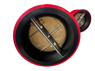
CF3M Wafer Dual Plate Check Valve
Description
Dual Plate Wafer Check Valve Technical Data Sheet
Project Name: ______________________
Tag Number: ______________________
Quantity: ______________________
1. General Specifications
| Item | Specification |
|---|---|
| Valve Type | Wafer Dual Plate Check Valve |
| Model | H76W-16P (or Manufacturer’s Standard) |
| Pressure Rating | PN16 (Equivalent to Class 150) |
| Nominal Size | DN50 – DN600 (NPS 2″ – 24″) Specify as required |
| End Connection | Wafer Type / Lug Type Select as required |
| Face to Face Dimension | API 594 / EN 558 Series 20 |
| Sealing Type | Metal-to-Metal Hard Seal |
| Medium | Water, Oil, Gas, and Corrosive Media (Compatible with CF3M) |
| Operating Temperature | -29°C to +425°C (-20°F to +800°F) |
| Body Material | ASTM A351 Grade CF3M (Equivalent to 316L Stainless Steel) |
| Disc (Plate) Material | ASTM A351 Grade CF3M (Equivalent to 316L Stainless Steel) |
| Shaft / Hinge Pin Material | ASTM A276 Type 316 / 316L Stainless Steel |
| Seat / Sealing Surface | Hard Facing (Stellite / Cobalt-based Alloy) on Body |
2. Bill of Materials (ASTM Standards)
| Part Name | Material | Material Grade / Specification | ASTM Standard |
|---|---|---|---|
| Body | Austenitic Stainless Steel | CF3M | ASTM A351 |
| Discs (Dual Plate) | Austenitic Stainless Steel | CF3M | ASTM A351 |
| Shaft / Hinge Pin | Precipitation Hardening / SS | 17-4PH / 316 SS | ASTM A564 / A276 |
| Seat Ring (Integral) | Hardfaced Alloy | Stellite (or equivalent) | – |
| Spring (Torsion) | High-Temperature Alloy | Inconel X-750 / 17-7PH | ASTM A638 / A693 |
| Locating Dowel Pin | Stainless Steel | Type 316 | ASTM F593 |
| Gasket / O-Ring (Opt.) | Flexible Graphite / Viton | – | – |
3. Technical Parameters & Performance
| Item | Unit | Value / Description |
|---|---|---|
| Pressure Testing | API 598 / ASME B16.34 | |
| – Shell Hydrostatic Test | psi (MPa) | 1.5 x PN (Appx. 348 psi / 2.4 MPa) |
| – High Pressure Seat Test | psi (MPa) | 1.1 x PN (Appx. 255 psi / 1.76 MPa) |
| – Low Pressure Pneumatic Test | psi (MPa) | 80 psi (0.6 MPa) |
| Operational Limits | ||
| – Max. Flow Velocity | ft/s (m/s) | Water: ≤ 16 ft/s (5 m/s); Gas: ≤ 164 ft/s (50 m/s) |
| – Closure Pressure | Backpressure prevents reverse flow. (Seat Leakage: Per API 598 / ISO 5208 Rate D for Metal Seats) | |
| Disc Action | Spring-assisted automatic closure. Recommended installation on horizontal lines with shaft vertical, or vertical lines with upward flow. |
4. Dimensions & Connection Data (Wafer Type, Units: mm / inches)
Note: Dimensions are for reference. Please refer to the specific manufacturer’s drawing for exact fit.
| Size DN (NPS) | Valve Length L (mm) | Flange Dia. D (mm) | Bolt Circle K (mm) | Recommended Bolts | Approx. Weight (kg) |
|---|---|---|---|---|---|
| 50 (2″) | 43 | 165 | 125 | 4 x M16 | ~2.5 |
| 80 (3″) | 64 | 200 | 160 | 8 x M16 | ~5.0 |
| 100 (4″) | 64 | 220 | 180 | 8 x M16 | ~7.5 |
| 150 (6″) | 76 | 285 | 240 | 8 x M20 | ~14.0 |
| 200 (8″) | 95 | 340 | 295 | 12 x M20 | ~25.0 |
| 250 (10″) | 114 | 405 | 355 | 12 x M24 | ~38.0 |
| 300 (12″) | 114 | 460 | 410 | 12 x M24 | ~55.0 |
| 350 (14″) | 127 | 520 | 470 | 16 x M24 | ~75.0 |
| 400 (16″) | 140 | 580 | 525 | 16 x M27 | ~95.0 |
5. Applicable Standards
-
Design & Manufacture: API 594, ASME B16.34
-
Face-to-Face: API 594, ISO 5752 Series 20
-
Flange Dimensions: ASME B16.5 (for Class 150), ASME B16.47
-
Pressure Testing: API 598, ISO 5208
-
Material (Body/Disc): ASTM A351 Grade CF3M
-
Material (Other): ASTM A276, ASTM A564, etc.
-
Marking: MSS SP-25
6. Remarks
-
Material Characteristics: ASTM A351 CF3M is the cast equivalent of UNS S31603 (316L) . It features ultra-low carbon content, providing excellent resistance to intergranular corrosion after welding and in chloride environments.
-
Metal Seated Feature: This valve features a Metal-to-Metal Hard Seal, making it suitable for high-temperature applications. The allowable leakage rate typically conforms to ISO 5208 Rate D(or API 598) for metal seats (a minute leakage is permissible; zero leakage is generally not guaranteed for standard metal seats).
-
Flow Direction: A permanent flow directional arrow is cast or marked on the valve body. Installation must align with the pipeline flow direction.
-
Installation Guidance: Best installed in horizontal pipelines with the shaft in a vertical position. For vertical installations, flow must be in the upward direction to allow the discs to open properly.