CPVC Lugged Butterfly Valve-DN250-PN16
Description
Technical Data Sheet (TDS)
CPVC Lugged Butterfly Valve with Worm Gear Operator
1. Product Description
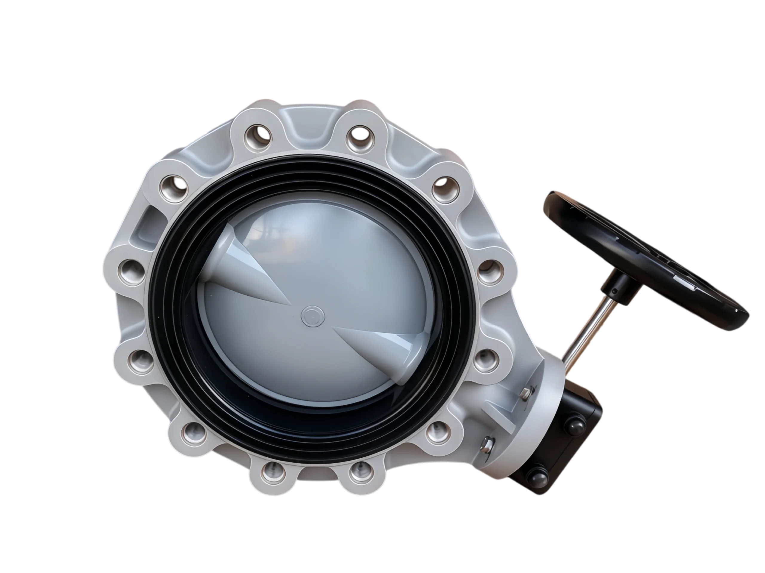
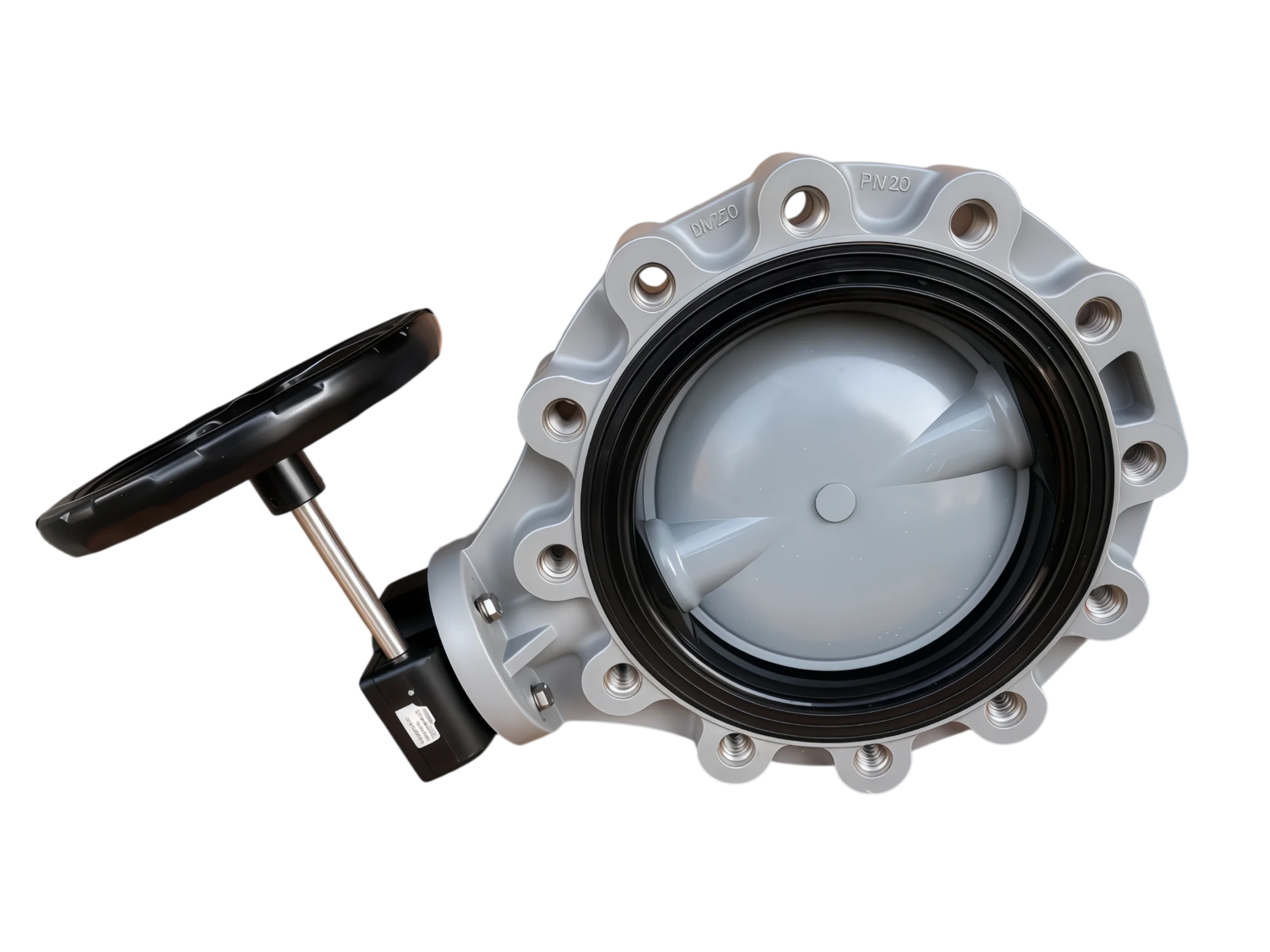
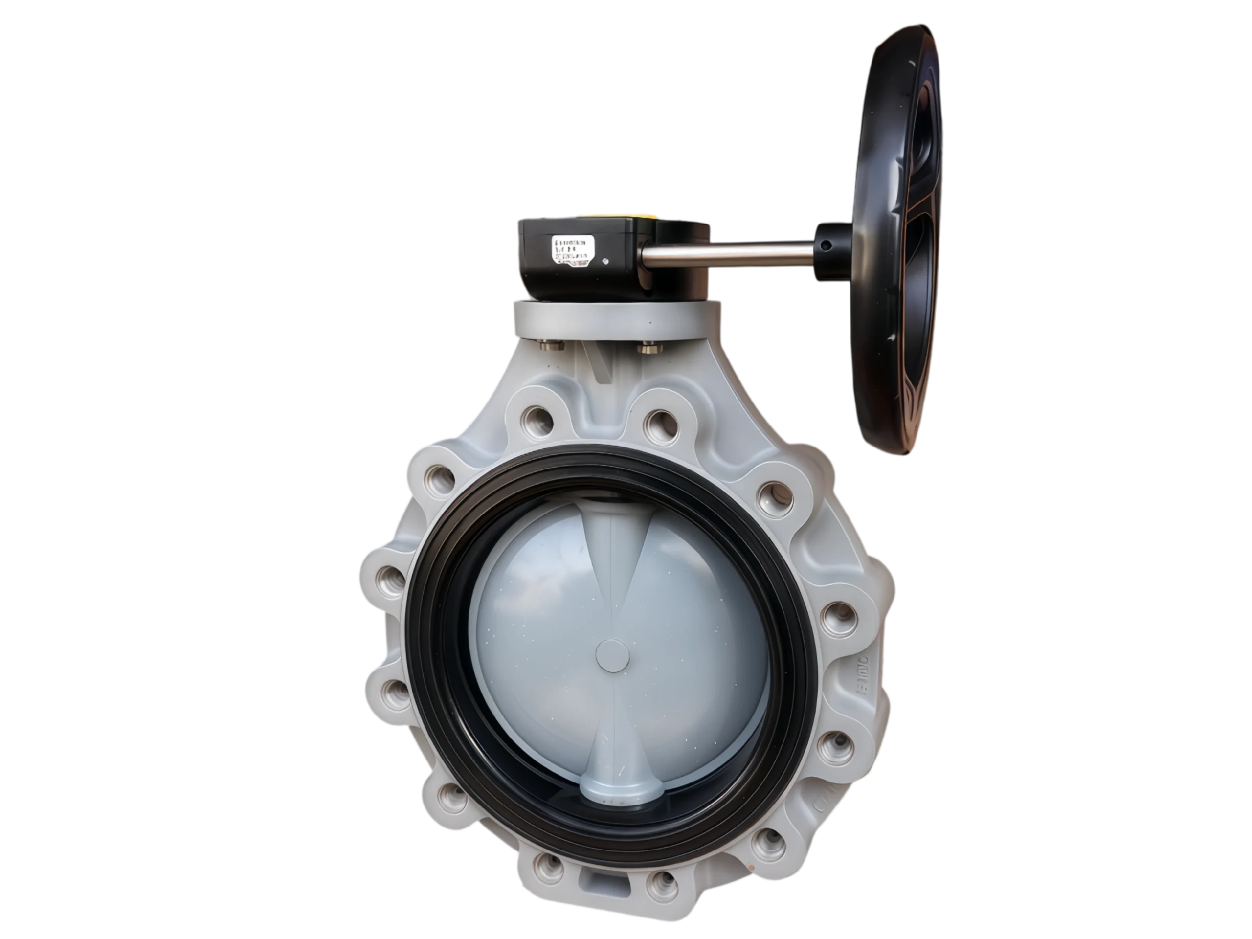
This product is a DN250, PN16 CPVC (Chlorinated Polyvinyl Chloride) Lugged Butterfly Valve with Threaded Holes, equipped with a Worm-Gear Handwheel operator. It is specifically designed for large-diameter (DN250 and above) thermoplastic and corrosive fluid piping systems. The valve provides reliable isolation and throttling control for hot water, oxidizing media (such as sodium hypochlorite), and medium-concentration hot acids at temperatures up to 90°C. The lugged design allows for single-flange dismantling and dead-end service, facilitating downstream maintenance without interrupting the upstream operation.
2. Key Features
-
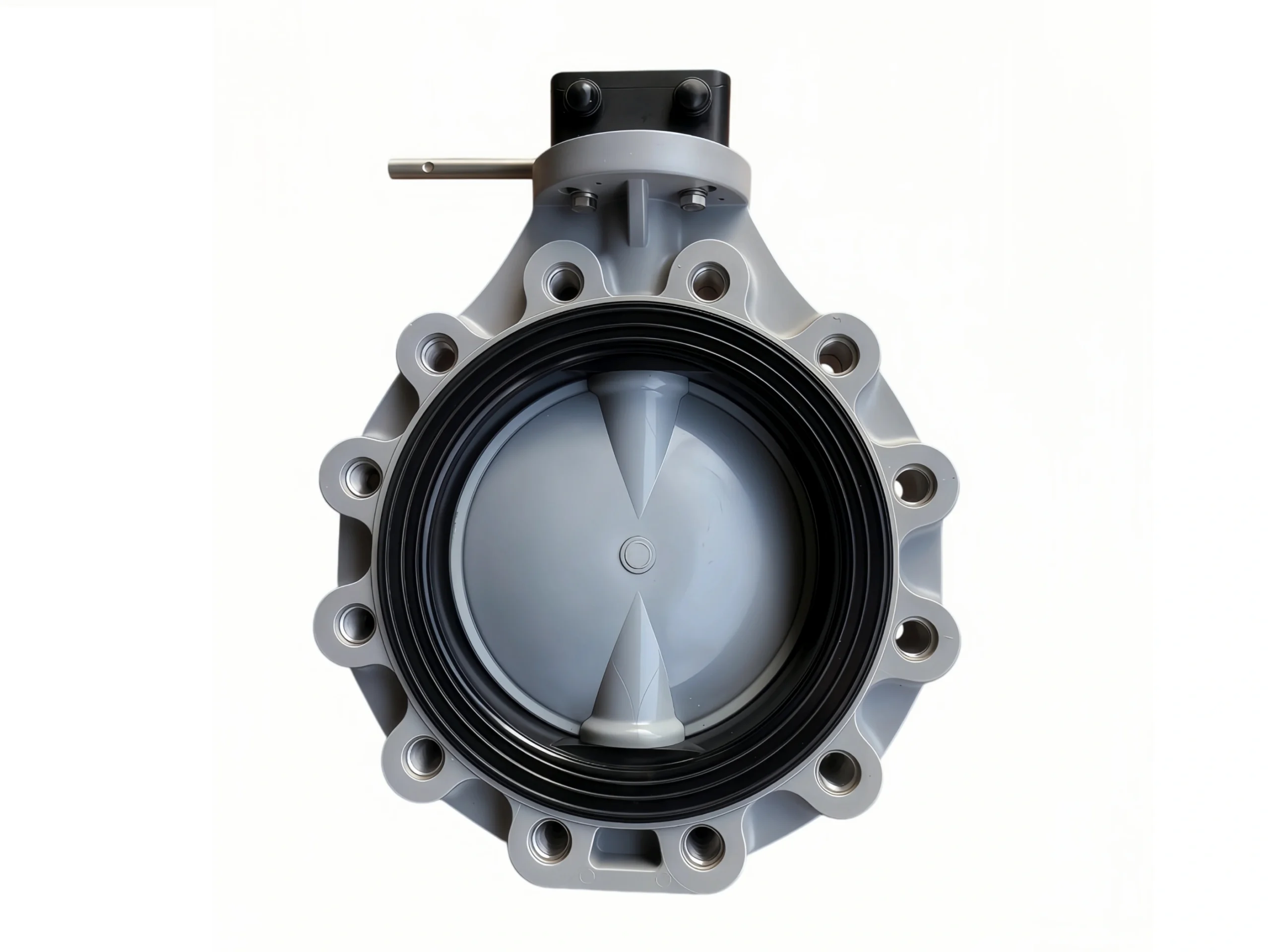
Lugged Threaded Connection: The valve body features threaded lug holes around the flange, allowing direct bolting to pipe flanges without the need for through-bolts and nuts. This supports independent installation and removal on a single side.
-
Worm-Gear Handwheel Operation: For the DN250 large diameter, the worm gear reduction handwheel mechanism reduces operating torque, ensuring labor-saving and precise open/close control.
-
All-CPVC Wetted Path: Both the valve body and disc are molded from CPVC resin, eliminating electrochemical corrosion and ensuring media purity.
-
Ribbed Body Design: The valve body is reinforced with external ribs and has no hollow sections, enhancing resistance to stress deformation under large-diameter, high-temperature conditions.
3. Material Specifications
| Component | Material | Standard / Remarks |
|---|---|---|
| Body / Disc | CPVC (Chlorinated Polyvinyl Chloride) | ASTM D1784 Cell Class 23447; Disc is the same material as the body |
| Seat / Seal | EPDM or FKM | EPDM for hot water/oxidizers; FKM for higher temperatures or chemical resistance |
| Stem | SS304 / SS316 Stainless Steel | Fully isolated from the media; compliant with ISO 5211 |
| Lug Inserts | Stainless Steel (AISI 316) | Threaded inserts pre-embedded in the CPVC lugs for high-strength flange fastening |
| Operator | Worm Gear + Handwheel | Cast iron/engineering plastic housing; Handwheel in ABS or PPG |
4. Dimensions & Connection Data (DN250, PN16)
Based on EN 558 / ISO 5752 long series (Series 16) and PN16 flange standards, the key connection dimensions are as follows:
| Parameter | Value | Standard Reference |
|---|---|---|
| Nominal Diameter (DN) | 250 (10″) | — |
| Nominal Pressure (PN) | 16 bar (1.6 MPa) | Based on 20°C water |
| Face-to-Face (L) | 68 mm (ISO 5752 Series 16 / EN 558 Line 16) | Long series standard for large diameters |
| Flange Outer Diameter (D) | 355 mm | PN16 Flange Standard |
| Bolt Circle Diameter (PCD) | 355 mm | PN16 Flange Standard |
| Bolt Holes & Thread | 12 × M20 (PN16) | Threads are machined directly into the stainless steel inserts |
| Top Drive Flange | ISO 5211 F10 | Pre-drilled 4×Ø12 holes for future electric/pneumatic actuator mounting |
Note: If adapting to ANSI Class 150 flanges, the threaded hole specification may be 12 × 7/8″-UNC. Please specify the flange standard when ordering.
5. Pressure & Temperature Ratings
| Parameter | Value | Remarks |
|---|---|---|
| Pressure Rating (20°C) | PN16 (16 bar) | Baseline for ambient temperature water |
| Max. Operating Temp. | 90°C | Limited by the elastomer seat (EPDM/FKM) |
| Temp-Pressure Derating | Derating required at elevated temps | E.g., allowable working pressure drops below 16 bar above 80°C. Refer to the CPVC derating curve. |
| Dead-End Service Pressure | Derated | Lugged design supports single-side pressure, but refer to manufacturer derating factors for dead-end service. |
6. Design & Testing Standards
| Item | Standard / Specification |
|---|---|
| Design Standard | API 609 / EN 593 / BS 5155 (Centric Soft-Seated Butterfly Valve) |
| Face-to-Face | ISO 5752 Series 16 / EN 558 Line 16 (DN250) |
| Flange Drilling | DIN 2501 PN16 / ISO 7005 PN16 (ANSI B16.5 Class 150 optional) |
| Top Flange | ISO 5211 F10 |
| Pressure Testing | API 598 / EN 12266-1 (Shell strength and seat tightness tests) |
7. Operation & Actuation
-
Standard Operator: The DN250 comes standard with a Worm-Gear Handwheel, driving a 90° stem rotation for opening, closing, and intermediate throttling. The gearbox typically includes a position indicator and travel limit stops.
-
Optional Actuation: The ISO 5211 F10 top flange allows for easy removal of the handwheel and mounting of electric or pneumatic actuators (F10 compliant connection kit required).
8. Installation Notes
-
Flange Alignment: Ensure parallel and concentric alignment of the mating pipe flanges before installation. Avoid forcing bolts through, which may damage the threaded inserts or the CPVC valve body.
-
Bolt Tightening: Apply suitable lubricant to the bolt threads. Tighten bolts evenly in a diagonal, cross-star sequence to the specified torque. Do not over-tighten to prevent damage to the CPVC lugs.
-
Dead-End Service: When used at the end of a pipeline or for single-side maintenance, ensure the downstream flange is blind-flanged or fully depressurized. Adhere to the dead-end service pressure limitations for lugged valves.
-
Thermal Expansion: In high-temperature piping systems, it is recommended to install expansion joints or flexible couplings on one side of the valve to minimize the impact of thermal stress on the CPVC body.
-
Media Compatibility: The chemical compatibility is ultimately determined by the seat material (EPDM/FKM). For strong solvents, concentrated acids, or alkalis, consult the chemical resistance chart and select an FKM seat if necessary.


