Double Block and Bleed (DBB) Sampling Ball Valve
Description
Technical Data Sheet (TDS)
Document No.: TDS-DBB-SV-001
Version: V1.0
Issue Date: October 3, 2026
Prepared by: Engineering Department
1. Product Identification
| Item | Description |
|---|---|
| Product Name | Double Block and Bleed (DBB) Sampling Ball Valve |
| Model Number | DBB-SV-2″-1500#-316 |
| Configuration | Double Block and Bleed (DBB) structure with integrated sampling probe and bleed valve |
| Valve Type | Flanged, Floating Ball DBB Valve |
| Nominal Size | 2″ (DN50) |
| Pressure Rating | Class 1500 (ASME B16.5) |
| Body Material | ASTM A351 CF8M / 316 Stainless Steel (Forged) |
| Applicable Media | Liquids, Gases, Chemicals |
| Main Application | In-line sampling, instrument isolation, chemical injection, process analysis |
2. Product Description
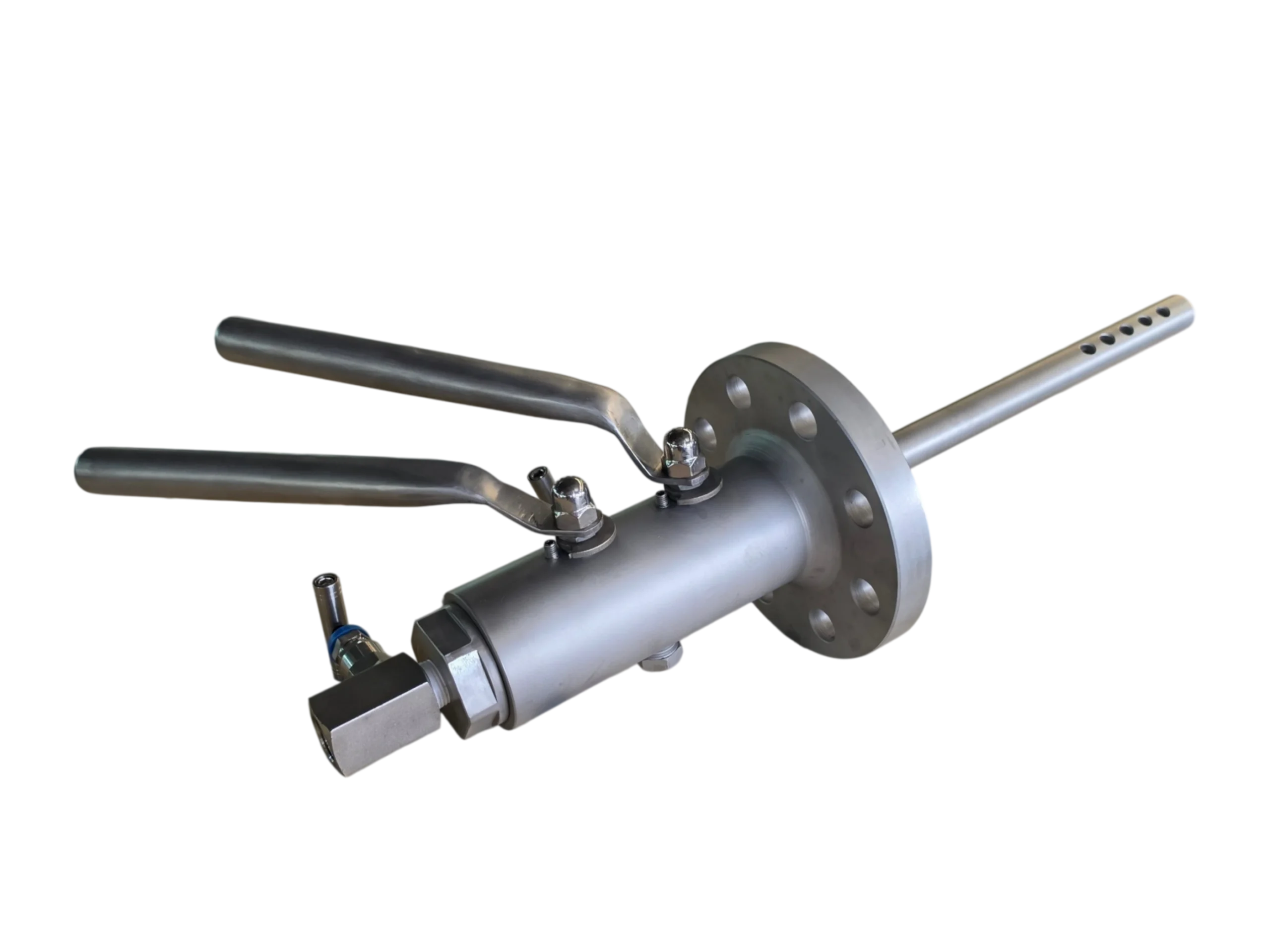
This product is a Flanged Double Block and Bleed (DBB) Sampling Ball Valve designed for 2″ Class 1500 service, with all wetted parts made of 316 Stainless Steel. The valve features a dual-ball tandem isolation structure, integrating two isolation ball valves into a single body, combined with a cavity bleed valve to provide the highest level of double isolation and safe depressurization.
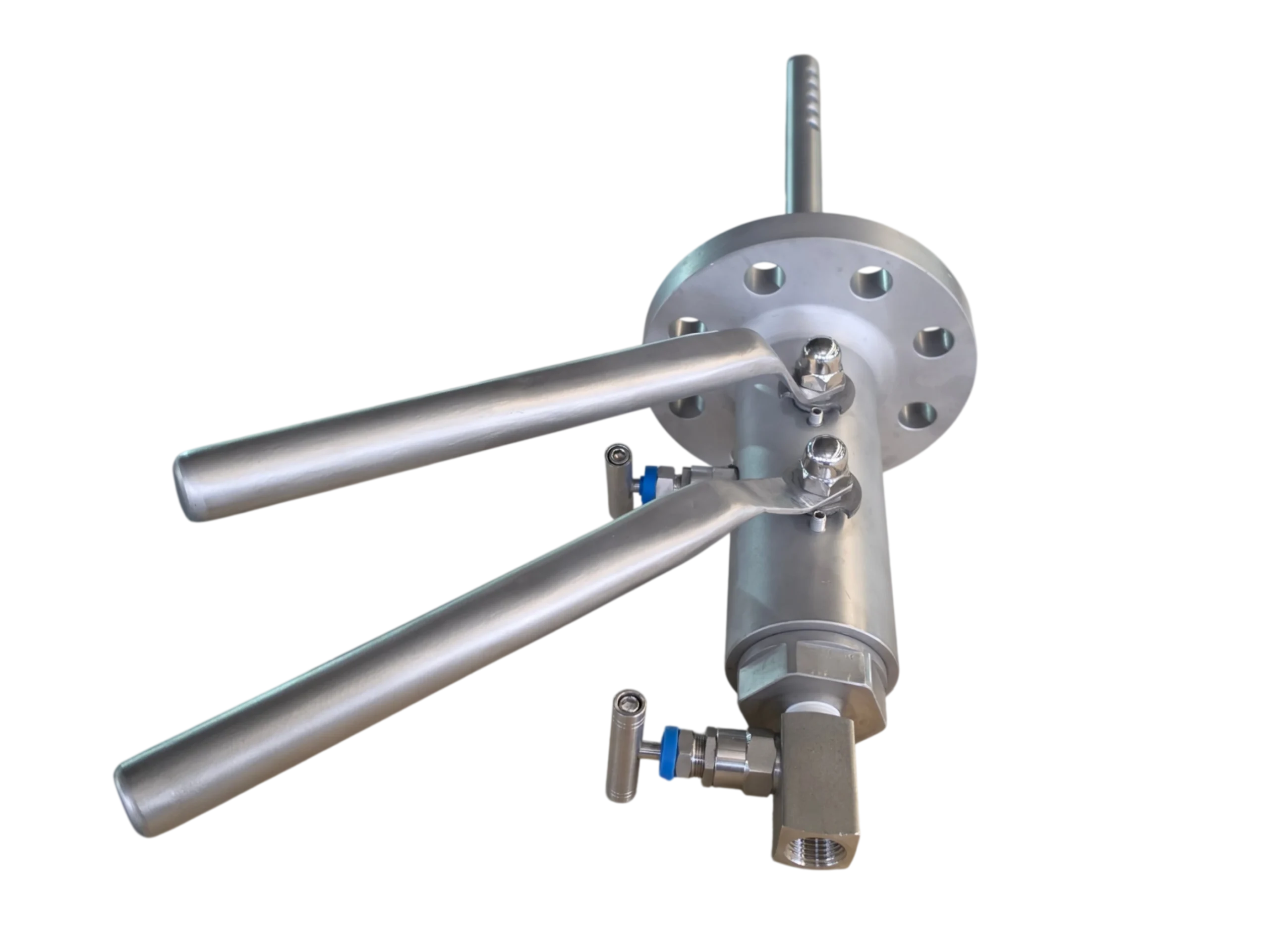
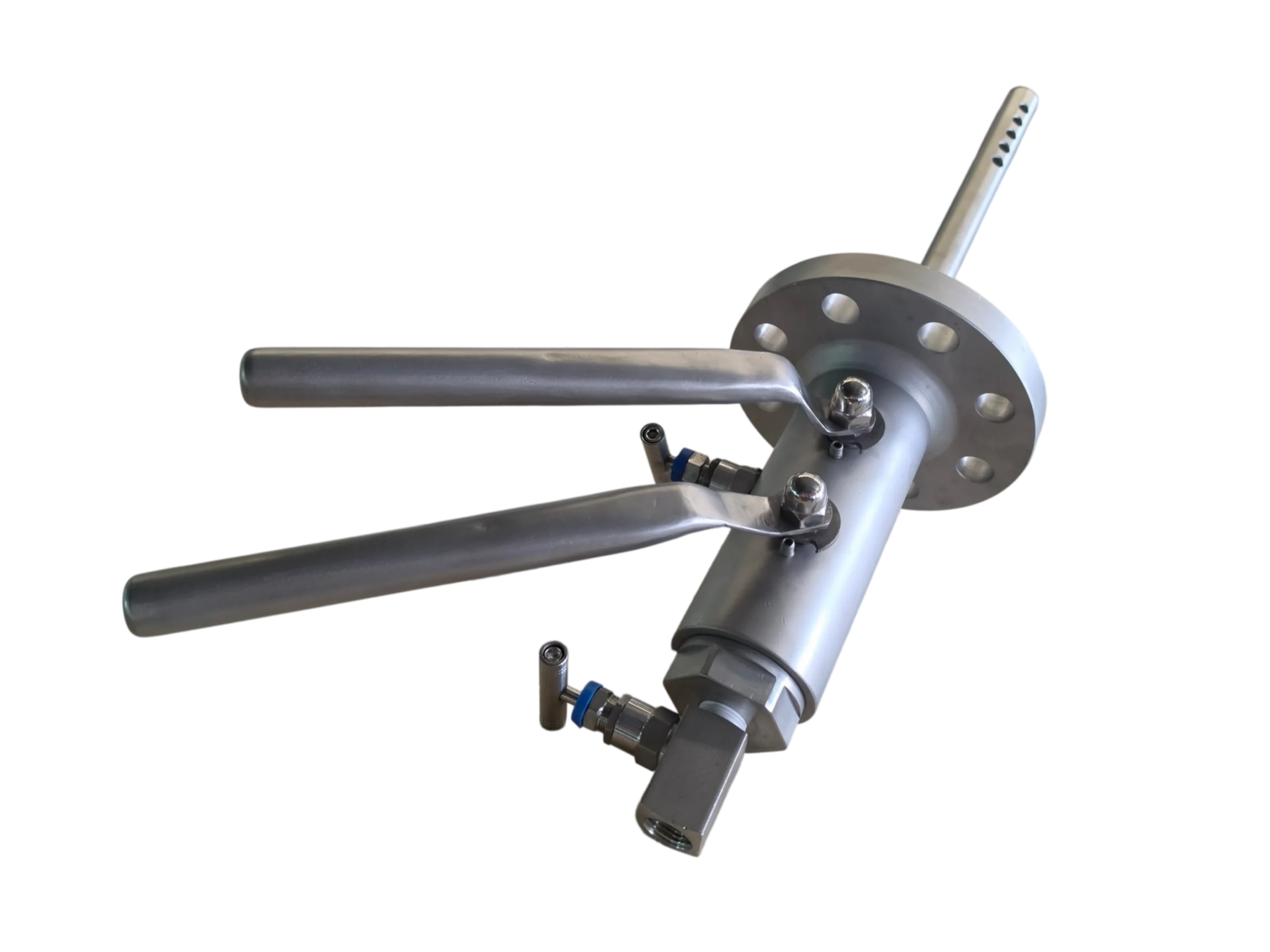
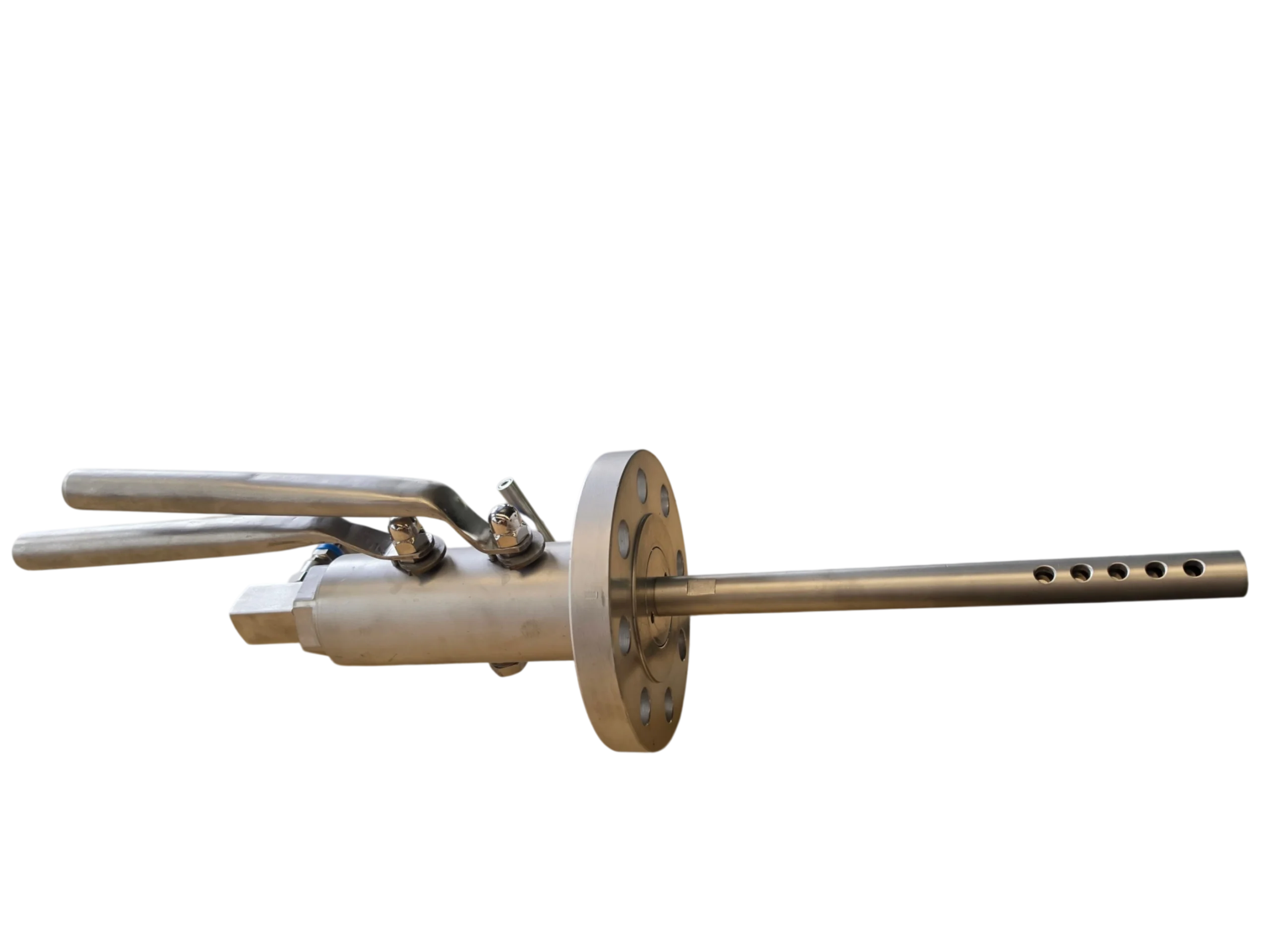
The inlet is equipped with an ASME B16.5 Class 1500 RF flange. The outlet integrates a sampling probe (extended sampling tube) with multiple equidistant sampling holes, enabling representative multi-point sampling within the pipeline. The valve body is equipped with dual operating handles, controlling the primary and secondary isolation ball valves respectively. The bleed valve assembly is located between the two ball valves, utilizing a needle-type globe valve for cavity depressurization, draining, or purging of the sampling line.
The design complies with API 6D, ASME B16.34, and ASME B16.5 standards, making it suitable for safe sampling and double isolation applications in petroleum, chemical, and natural gas industrial processes.
3. Technical Parameters
3.1 Basic Parameters
| Item | Parameter |
|---|---|
| Nominal Size | 2″ (DN50) |
| Pressure Rating | Class 1500 |
| Max. Cold Working Pressure | Approx. 25.0 MPa (3625 psi) @ 38°C |
| Design Temperature Range | -29°C to +200°C |
| Design Standard | API 6D / ASME B16.34 |
| Flange Standard | ASME B16.5 |
| Face-to-Face Dimension | Per ASME B16.10 or manufacturer’s standard |
| Testing & Inspection | API 598 / ISO 5208 |
3.2 Material Parameters
| Component | Material | Standard |
|---|---|---|
| Body / Bonnet | 316 Stainless Steel (CF8M / Forged) | ASTM A351 / A182 |
| Ball | 316 SS + Hard Alloy Coating | ASTM A276 |
| Stem | 316 Stainless Steel | ASTM A276 |
| Seat Ring | PTFE / RPTFE / Metal-to-Metal | — |
| Packing | Flexible Graphite | — |
| Sampling Probe | 316 Stainless Steel | — |
| Bleed Valve | 316 SS Needle Valve | — |
| Fasteners | A4-70 (316 Stainless Steel) | — |
316 SS Chemical Composition (Reference): C ≤ 0.08%, Si ≤ 1.00%, Mn ≤ 2.00%, P ≤ 0.035%, S ≤ 0.03%, Ni: 10.0-14.0%, Cr: 16.0-18.5%, Mo: 2.0-3.0%.
316 SS Mechanical Properties (Reference): Tensile Strength ≥ 620 MPa, Yield Strength ≥ 310 MPa, Elongation ≥ 30%, Density 8.03 g/cm³.
3.3 Flange Connection Dimensions (2″ Class 1500 ASME B16.5)
| Item | Dimension |
|---|---|
| Flange OD | 215.9 mm (8.50″) |
| Number of Bolt Holes | 8 |
| Bolt Hole Diameter | 25.4 mm (1″) |
| Bolt Circle Diameter | 165.1 mm (6.50″) |
| Face Type | Raised Face (RF) |
3.4 Sampling Probe Parameters
| Item | Parameter |
|---|---|
| Probe OD | Φ18–22 mm (Typical, subject to design) |
| Probe Length | 250–350 mm (Typical, customizable) |
| Number of Sampling Holes | 6–10 equidistant holes |
| Sampling Hole Diameter | Φ3–5 mm |
| Hole Arrangement | Uniformly distributed along the probe axis |
| Probe Material | 316 Stainless Steel |
4. Structural Features
-
Double Block and Bleed (DBB) Structure: Two independent ball valves in series within a single body, forming a double isolation barrier. The intermediate cavity is equipped with a bleed port, meeting the highest safety isolation requirements.
-
Anti-Blowout Stem: The stem is designed with an anti-blowout structure to ensure it will not be ejected under extreme pressure conditions.
-
Anti-Static Device: Anti-static grounding is provided between the ball, stem, and body to eliminate static electricity buildup risks.
-
Dual Operating Handles: Each ball valve is equipped with an independent handle for 90° quick opening and closing.
-
Integrated Sampling Probe: The outlet is equipped with a multi-hole sampling probe, allowing simultaneous sampling at different depths within the pipeline for improved sample representativeness.
-
Needle Bleed Valve: The intermediate cavity is equipped with a 316 SS needle-type globe valve for cavity depressurization, draining, and purging of the sampling line.
-
Fire-Safe Design: Complies with API 607 / API 6FA fire test requirements (optional).
-
Low Fugitive Emissions: Can meet ISO 15848 low fugitive emission requirements (optional).
5. Operating Instructions
-
Pre-Sampling Preparation: Confirm the valve is in the closed position and check that the bleed valve is closed.
-
Open Primary Ball Valve: Rotate the first handle 90° to the open position, allowing media to enter the intermediate cavity.
-
Open Secondary Ball Valve: Rotate the second handle 90° to the open position, allowing media to flow through the sampling probe.
-
Sampling Operation: After the media flows steadily, collect the sample at the probe outlet using a sampling container.
-
Post-Sampling Closing: Close the secondary ball valve first, then close the primary ball valve.
-
Intermediate Cavity Bleed: After sampling, open the needle bleed valve to drain any residual media in the intermediate cavity, ensuring double isolation safety.
-
Reset: Close the bleed valve and confirm all handles are in the closed position.
6. Safety & Health
| Item | Description |
|---|---|
| Hazard Classification | Non-hazardous (valve body); observe media-specific precautions during operation |
| Eye Contact | If media splashes into eyes, rinse immediately with plenty of water for at least 15 minutes and seek medical attention |
| Skin Contact | Remove contaminated clothing and wash affected area with soap and water |
| Inhalation | Move to fresh air, keep respiratory passages clear, seek medical attention if necessary |
| Ingestion | Rinse mouth, do not induce vomiting, seek medical attention immediately |
| Personal Protection | Wear protective gloves, goggles, and protective clothing; wear respiratory protection when handling toxic or corrosive media |
| Operating Precautions | Ensure the bleed port is directed to a safe direction during sampling; avoid direct contact with the valve body under high-temperature conditions |
For detailed safety information, please refer to the SDS/MSDS of the corresponding media.
7. Storage & Maintenance
-
Storage Conditions: Store in a dry, ventilated indoor environment, avoiding moisture and corrosive gases.
-
Storage Temperature: -20°C to +50°C.
-
Protection Measures: Apply anti-rust grease to flange sealing surfaces and cover with protective caps.
-
Packaging: Wooden case packaging with moisture-proof lining.
-
Maintenance Cycle: Routine inspection recommended every 12 months or every 2,000 operations.
-
Maintenance Items: Check packing sealing, seat sealing, handle operation flexibility, and anti-static continuity.
-
Seal Replacement: If leakage is found, stop using the valve and replace seals. Replacement must be performed by qualified personnel.
8. Inspection & Testing
| Test Item | Standard | Requirement |
|---|---|---|
| Shell Strength Test | API 598 | 1.5 times rated pressure, no leakage |
| High-Pressure Seat Test | API 598 | 1.1 times rated pressure, no visible leakage |
| Low-Pressure Seat Test | API 598 | 0.4–0.7 MPa air pressure, no bubbles |
| Cavity Test | API 6D | Verify DBB function |
| Operating Torque Test | — | Record full-stroke operating torque |
9. Packaging & Transportation
| Item | Description |
|---|---|
| Packaging Type | Wooden Case |
| Unit Weight | Approx. 35–50 kg (Depending on final design) |
| Transportation Method | General Freight |
| Transportation Requirements | Prevent collision and rain exposure; keep valve upright |
10. Regulations & Compliance
-
Design Standard: API 6D, ASME B16.34
-
Flange Standard: ASME B16.5
-
Testing Standard: API 598, ISO 5208
-
Fire-Safe Standard: API 607 / API 6FA (Optional)
-
Low Fugitive Emission Standard: ISO 15848 (Optional)
-
Pressure Equipment Directive: PED 2014/68/EU (If applicable)
11. Version History
| Version | Date | Revision Description | Prepared/Revised by |
|---|---|---|---|
| V1.0 | October 3, 2026 | Initial Release | — |
12. Disclaimer
The information provided in this Technical Data Sheet is based on current product design and manufacturing standards and is for reference only. Actual dimensions, weights, and performance parameters may vary depending on specific designs, material batches, and operating conditions. Users should confirm actual conditions prior to selection and installation and verify final technical parameters with the manufacturer. The manufacturer assumes no liability for direct or indirect damages arising from conditions of use beyond its control.


