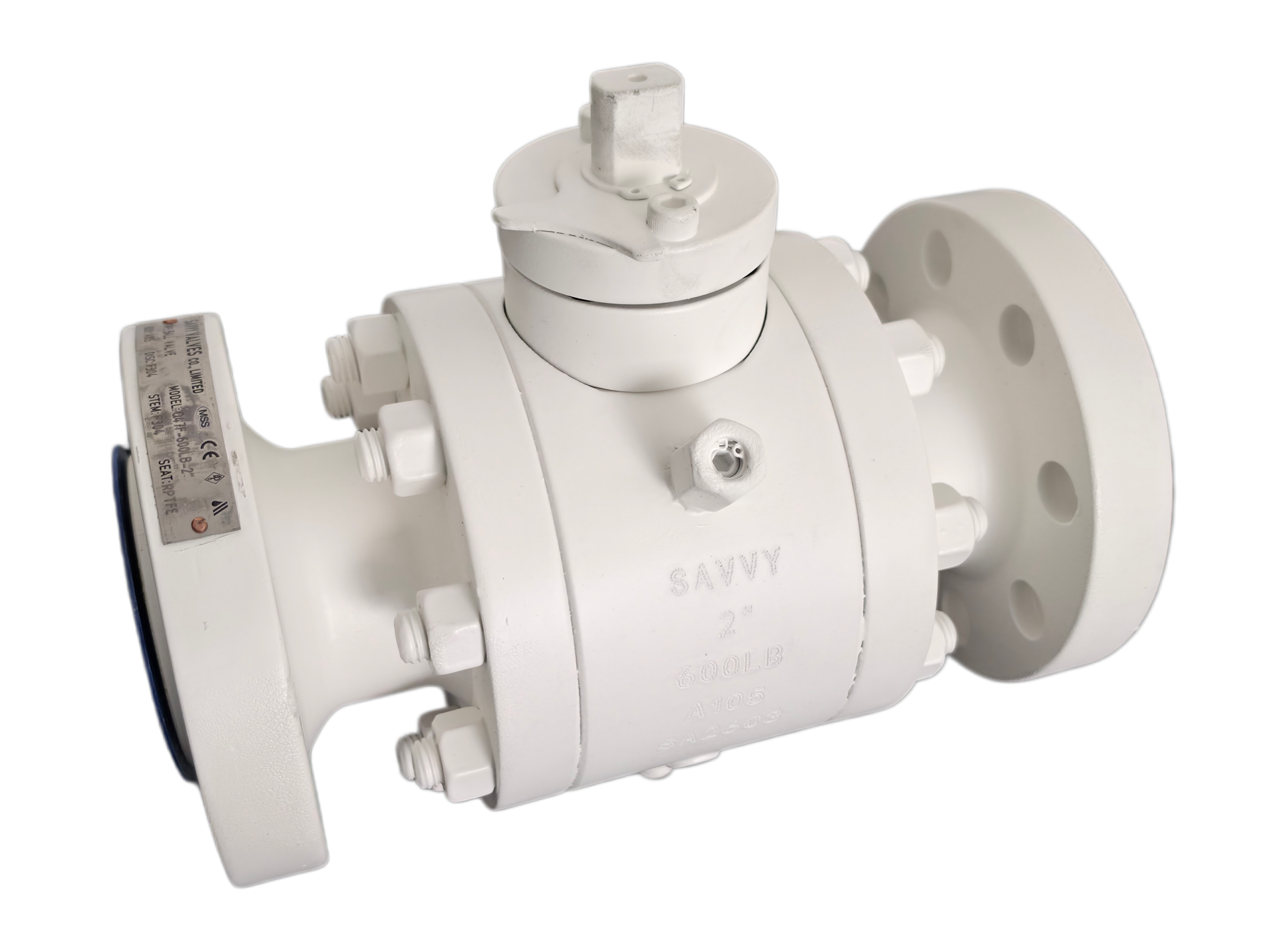
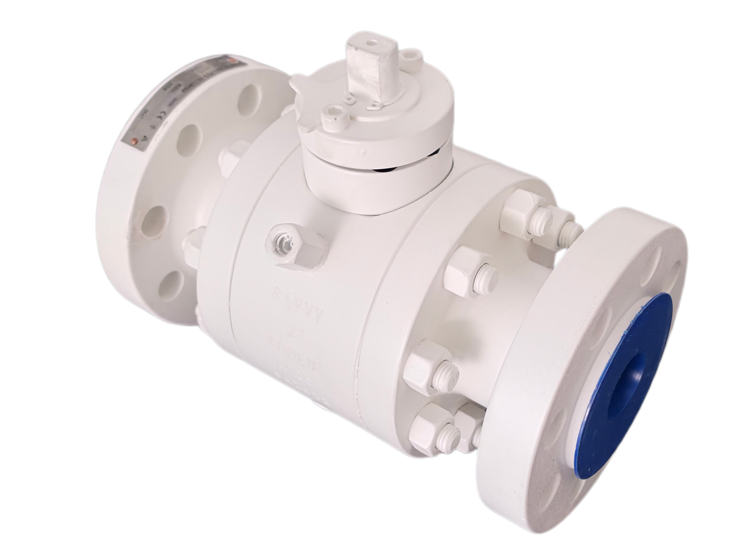
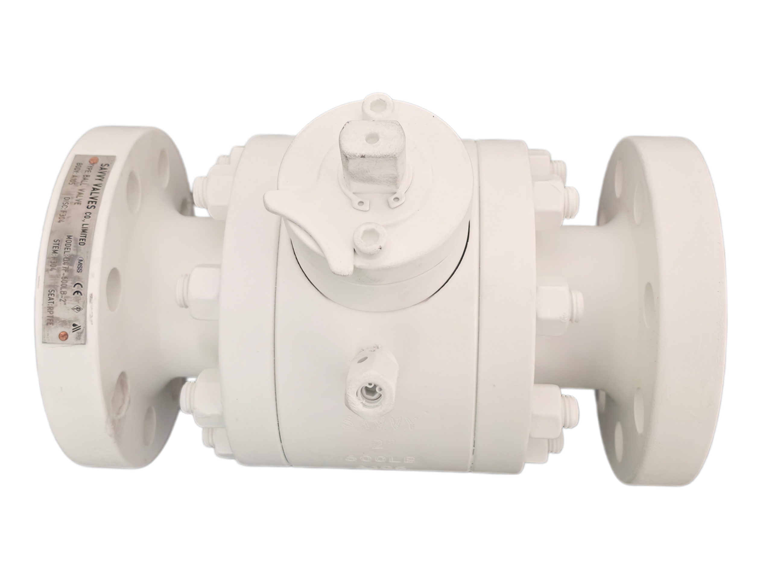
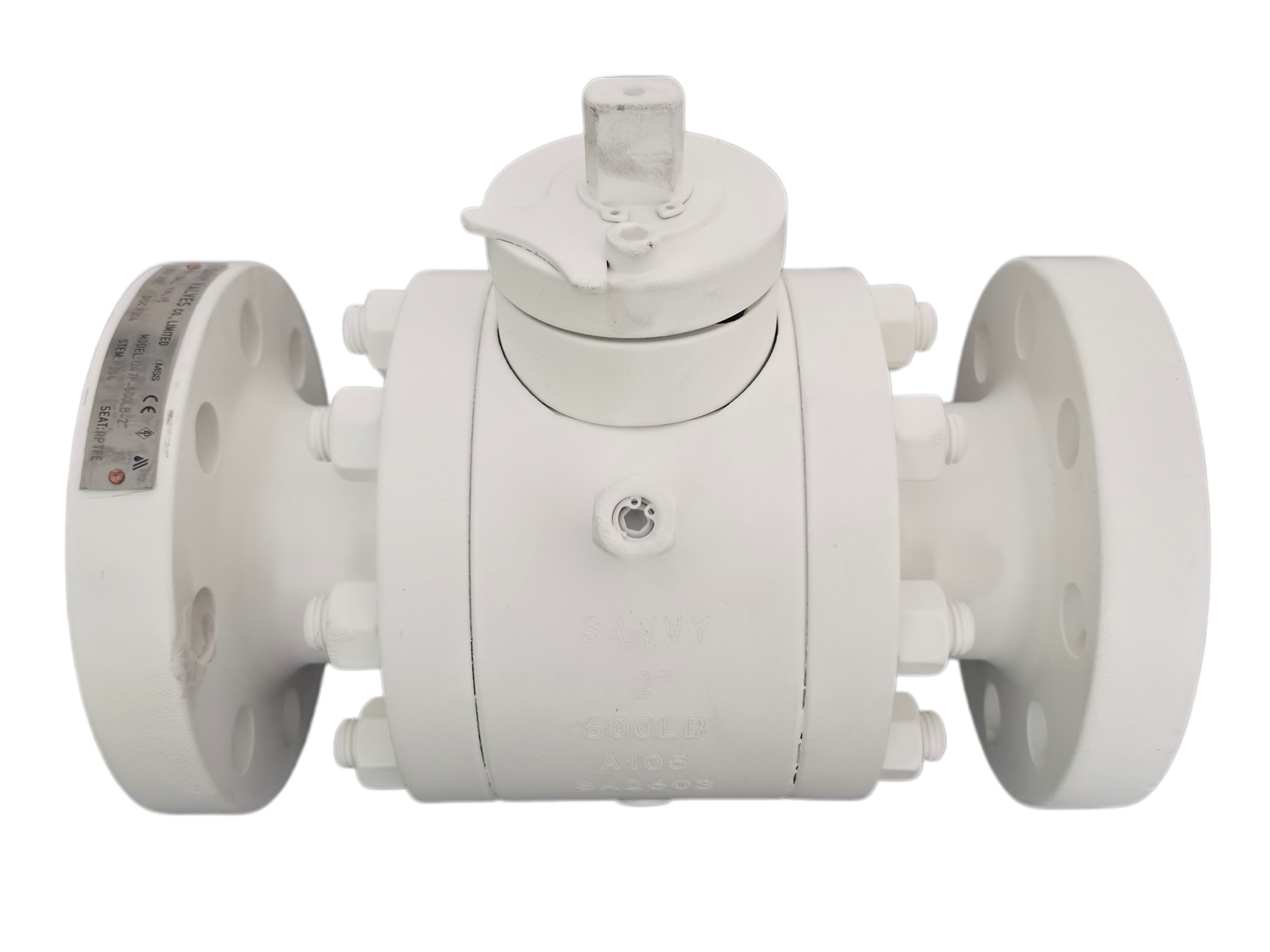
2″ 600LB 2-Piece Free Forged Trunnion Ball Valve
Description
TECHNICAL DATA SHEET
2″ 600LB Two-Piece Free Forged Trunnion Ball Valve
1. General Information
| Item | Standard Configuration | User Specification / Remarks |
|---|---|---|
| Valve Type | 2-Piece Body, Trunnion Mounted, Side Entry, Free Forged | |
| Nominal Size | NPS 2″ (DN50) | |
| Pressure Rating | ASME Class 600 LB (PN100) | |
| End Connection | Raised Face Flange (RF) / Butt Weld (BW)(请选择) | |
| Operation Type | Lever / Wrench / Gearbox / Pneumatic Actuator / Electric Actuator(请选择) | |
| Design & Manufacture Standard | API 6D, ASME B16.34, ISO 17292 | |
| Face-to-Face Dimension | ASME B16.10, API 6D | |
| Flange Dimension | ASME B16.5 (NPS ≤ 24″) | |
| Butt Weld End | ASME B16.25 | |
| Wall Thickness | ASME B16.34 | |
| Pressure Testing | API 6D, API 598, ISO 5208 | |
| Fire Safe Design | API 607, API 6FA, ISO 10497 | |
| Anti-Static Device | Yes (BS 5353 / ISO 17292) | |
| Fugitive Emission | ISO 15848-1 (Optional) | |
| NACE Compliance | NACE MR0175 / ISO 15156 (Optional) | |
| SIL Rating | SIL 3 Capable (IEC 61508) | |
| Quality System | API 6D Monogram, PED/TPED, ATEX (Optional) |
This 2″ 600LB two-piece trunnion-mounted ball valve is engineered for demanding isolation and flow control applications in oil & gas, petrochemical, chemical, power generation, and long-distance pipeline services. Featuring a robust two-piece bolted body construction with fixed ball trunnion design, it provides bidirectional bubble-tight shutoff, reduced operating torque, and extended service life under high pressure conditions.
2. Key Design Features
1) Two-Piece Bolted Body Construction
Robust body/bonnet bolted connection, suitable for high-pressure classes; options for ring gasket, spiral wound gasket, or lip seal ring.
2) Trunnion-Mounted Ball
Fixed ball design with lower trunnion support and upper anti-blowout stem; absorbs line pressure thrust, significantly reduces operating torque.
3) Double Block & Bleed (DBB) Capability
Standard design enables simultaneous isolation from both upstream and downstream, with cavity pressure relief and bleed functionality.
4) Dual Piston Effect (DPE) / Single Piston Effect (SPE) Seats
Flexible seat configurations available; Inconel®-energized springs ensure low-pressure sealing.
5) Fire-Safe & Anti-Static
Compliant with API 607/6FA and BS 5353; blowout-proof stem and anti-static device standard.
6) Low Fugitive Emission Packing
Live-loaded disc spring packing system; optional ISO 15848-1 compliance.
7) Full Traceability
Positive Material Identification (PMI) and EN 10204 Type 3.1 certification available.
3. Design Standards & Specifications
| Item | Standard / Code |
|---|---|
| Design & Manufacture | API 6D, API 608, ASME B16.34, ISO 17292 |
| Face-to-Face Dimension | ASME B16.10, API 6D |
| End Connections | ASME B16.5 (RF/RTJ), ASME B16.25 (BW), EN 1092-1, MSS SP-44 |
| Pressure Testing | API 6D, API 598, ISO 5208 |
| Fire Safe | API 607, API 6FA, ISO 10497, BS 6755 Part 2 |
| Fugitive Emission | ISO 15848-1, TA-Luft (optional) |
| Anti-Static | BS 5353, ISO 17292 |
| NACE | MR0175 / ISO 15156 (optional) |
| SIL Rating | SIL 3 Capable (IEC 61508) |
| Quality System | API 6D Monogram, PED/TPED, ATEX |
4. General Technical Parameters
| Parameter | Specification |
|---|---|
| Valve Type | Two-Piece Trunnion Mounted, Bolted Body, Side Entry |
| Nominal Size | NPS 2″ (DN50) |
| Pressure Class | ASME Class 600 LB (PN100) |
| Flow Pattern | Full Bore (Standard) / Reduced Bore (Optional)(请选择) |
| Flow Direction | Bidirectional (Standard); Uni-directional with cavity relief (Optional) |
| Temperature Range | -29°C ~ +120°C (Soft Seated, PTFE/RPTFE) |
| -29°C ~ +230°C (PPL/Devlon) | |
| -40°C ~ +560°C (Metal Seated, Hardfaced) | |
| Service Media | Water, Oil, Natural Gas, Refined Products, Sour Gas (NACE), Chemical Slurries, Steam, High-Purity Gases |
| Leakage Rate | API 598 Zero Leakage (Soft-Seated) |
| Flow Characteristic | On-Off (Quick Opening) |
| Sealing Method (Stem) | Packing + O-Ring |
| DBB Function | Yes (Double Block and Bleed) |
| Operation | Manual (Lever), Pneumatic (DA/SR), Electric, Hydraulic, Gas-over-Oil |
| Mounting | ISO 5211 Top Flange for Actuator Mounting |
5. Bill of Materials (Main Components)
| No. | Part Name | Material / Grade | Optional Material / Remarks |
|---|---|---|---|
| 1 | Body (Free Forged) | ASTM A105 / A105N (Carbon Steel) | ASTM A350 LF2 (Low Temp); ASTM A182 F304/F316 (Stainless Steel) |
| 2 | Bonnet / Tailpiece (Free Forged) | ASTM A105 / A105N | Same as Body |
| 3 | Ball | ASTM A105 + ENP (Electroless Nickel Plating) / A182 F304 / A182 F316 | Stainless Steel + Hardened |
| 4 | Seat Insert (Soft Seal) | PTFE / RPTFE / PPL | Nylon, Devlon, PEEK, or Metal Sealing |
| 5 | Seat Support Ring | ASTM A105 / A182 F304 | |
| 6 | Seat Spring | Inconel X-750 / 17-7PH | For seat pre-load |
| 7 | Stem | ASTM A276-410 (Stainless Steel) / A182 F304 / 17-4PH | |
| 8 | Stem Bearing / Thrust Washer | PTFE + Stainless Steel / Self-lubricating | |
| 9 | Body Gasket | PTFE / Flexible Graphite + Stainless Steel / Spiral Wound | |
| 10 | O-Ring / Seal Ring | NBR / Viton / FKM | |
| 11 | Stud Bolt | ASTM A193 B7 | |
| 12 | Hex Nut | ASTM A194 2H | |
| 13 | Packing | PTFE / Graphite | |
| 14 | Anti-Static Spring | Stainless Steel | Between stem and ball, stem and body |
| 15 | Stem O-Ring | Viton / NBR | |
| 16 | Trunnion Plate / Thrust Plate | ASTM A105 + ENP / Stainless Steel |
6. Body Material — ASTM A105/A105N
As a 2″ free forged carbon steel valve, the body and bonnet shall be manufactured from ASTM A105 or A105N (normalized) forged carbon steel. This material is classified under ASME B16.34 Material Group 1.1, suitable for general carbon steel service.
6.1 Chemical Composition (ASTM A105/A105N)
| Element | Composition (Weight %) |
|---|---|
| Carbon (C) | 0.35 max |
| Manganese (Mn) | 0.60 – 1.05 |
| Silicon (Si) | 0.10 – 0.35 |
| Phosphorus (P) | 0.035 max |
| Sulfur (S) | 0.040 max |
| Copper (Cu) | 0.40 max |
| Nickel (Ni) | 0.40 max |
| Chromium (Cr) | 0.30 max |
| Molybdenum (Mo) | 0.12 max |
| Vanadium (V) | 0.08 max |
6.2 Mechanical Properties (ASTM A105/A105N)
| Property | Requirement |
|---|---|
| Tensile Strength (σb) | ≥ 485 MPa |
| Yield Strength (σs) | ≥ 250 MPa |
| Hardness | ≤ HB 187 |
| Elongation | ≥ 22% (typical) |
7. Pressure-Temperature Ratings (Per ASME B16.34, Material Group 1.1)
The following table provides the maximum allowable working pressure at various temperatures for ASME Class 600 valves manufactured from ASTM A105 carbon steel (Material Group 1.1 per ASME B16.34).
| Temperature | Maximum Allowable Working Pressure |
|---|---|
| -29°C ~ 38°C (-20°F ~ 100°F) | 1,480 psig (102.0 barg / 10.2 MPa) |
| 100°C (212°F) | 1,480 psig (102.0 barg / 10.2 MPa) |
| 150°C (302°F) | 1,480 psig (102.0 barg / 10.2 MPa) |
| 200°C (392°F) | 1,340 psig (92.4 barg / 9.24 MPa) |
| 250°C (482°F) | 1,200 psig (82.7 barg / 8.27 MPa) |
| 300°C (572°F) | 1,080 psig (74.5 barg / 7.45 MPa) |
| 350°C (662°F) | 900 psig (62.1 barg / 6.21 MPa) |
| 400°C (752°F) | 680 psig (46.9 barg / 4.69 MPa) |
Notes:
-
At ambient temperature (-29°C to 38°C), a Class 600 carbon steel valve has a maximum working pressure of approximately 1,480 psig (102.1 barg).
-
The maximum allowable working pressure decreases as the temperature increases due to reduced material allowable stress.
-
The actual operating pressure shall NOT exceed the tabulated value at the design temperature.
-
For specific project requirements involving different material groups or temperature ranges, please consult the ASME B16.34 standard or contact the manufacturer.
8. Test & Inspection
8.1 Test Pressure (Unit: MPa)
| Pressure Rating | Shell (Hydrostatic) | Seat (High Pressure Hydro.) | Low Pressure Pneumatic |
|---|---|---|---|
| Class 150 | 3.0 MPa | 2.2 MPa | 0.6 MPa |
| Class 300 | 7.6 MPa | 5.6 MPa | 0.6 MPa |
| Class 600 | 15.0 MPa | 11.0 MPa | 0.6 MPa |
Note: Specific values shall be performed per API 6D / API 598. The shell hydrostatic test pressure for Class 600 carbon steel valves is 154 bar (15.4 MPa) per API 598. The seat high pressure test pressure for Class 600 is 110.3 bar.
8.2 Inspection Requirements
| Inspection Item | Standard / Acceptance Criteria |
|---|---|
| Visual / Dimensional Inspection | As per drawings and relevant ASME standards |
| Hydrostatic Shell Test | API 6D / API 598; Duration as per standard |
| Hydrostatic Seat Test | API 6D / API 598; Zero leakage for soft-seated valves |
| Low Pressure Pneumatic Seat Test | API 6D / API 598; 0.6 MPa |
| Positive Material Identification (PMI) | As per EN 10204 Type 3.1 |
| NDE (PT / MT / UT / RT) | Optional as per ASME B16.34 / ASME BPVC Section V |
| Fire Safe Test (if required) | API 607 / API 6FA |
| Fugitive Emission Test (if required) | ISO 15848-1 |
| NACE Compliance (if required) | NACE MR0175 / ISO 15156 |
9. Dimensions & Weight
9.1 Face-to-Face Dimension (ASME B16.10)
| NPS | Pressure Class | L – Face-to-Face (RF Flanged) mm |
|---|---|---|
| 2″ (DN50) | Class 600 | 292 |
Note: Face-to-face dimension is per ASME B16.10. For butt weld ends (BW), the dimension may differ from flanged ends.
9.2 Approximate Overall Dimensions
| NPS | Pressure Class | H (Centerline to Top of Stem, mm) | Approx. Weight (kg) |
|---|---|---|---|
| 2″ (DN50) | Class 600 | Approx. 160 ~ 200 | Approx. 25 ~ 40 |
Note: The exact dimensions, flange facing finish, and weight depend on end connection type and specific design/manufacturer. Please refer to the manufacturer‘s certified general arrangement drawing or confirm with the manufacturer for specific project requirements.
10. Scope of Supply & Optional Configurations
| Item | Standard Scope | Optional Upgrade / Alternative |
|---|---|---|
| Body Material | ASTM A105 / A105N (Forged Carbon Steel) | ASTM A350 LF2 (Low Temp Carbon Steel); ASTM A182 F304 / F316 (Stainless Steel); ASTM A182 F51 / F53 / F55 (Duplex / Super Duplex Stainless Steel) |
| Ball Material | ASTM A105 + ENP | A182 F304, A182 F316, Duplex SS |
| Soft Seat Material | PTFE (-29°C ~ +120°C) | RPTFE (-29°C ~ +150°C), PPL (-29°C ~ +250°C), Devlon, PEEK, Nylon |
| Hard Seat Material | — | Tungsten Carbide Coating, Stellite Overlay, Chrome Carbide, Metal-to-Metal Sealing (-40°C ~ +560°C) |
| Stem Material | ASTM A276 410 (13Cr SS) | A182 F304, A182 F316, 17-4PH, Inconel 718 |
| Fire Safe | API 607 / API 6FA (API 6D Standard) | ISO 10497, BS 6755 Part 2 |
| Fugitive Emission | Standard Packing | ISO 15848-1, TA-Luft Certified Packing |
| NACE Compliance | N/A | NACE MR0175 / ISO 15156 (for sour gas / H₂S service) |
| End Connection | RF Flanged / BW | RTJ Flanged, Hub Connection, Combination |
| Operation | Manual Lever (Standard) | Gear Operator, Pneumatic (Spring Return / Double Acting), Electric Actuator, Hydraulic, Gas-over-Oil |
| DBB Function | Yes (Cavity Relief / Bleed Standard) | |
| Cavity Over-Pressure Protection | Yes (Self-Relieving Seats) | External Relief Valve |
| Certification | EN 10204 3.1 (Mill Test Certificate) | EN 10204 3.2 (Third-Party Inspection), API 6D Monogram, PED/TPED, ATEX |
| Locking Device | Not included as standard | Locking lever / Lockable gear operator |
| Stem Extension | Not included as standard | Extended stem for buried / cryogenic service |
| Drain / Vent Valve | Optional | Provided as per specification requirement |
| Valve Position Indicator | Not included as standard | Visual position indicator, limit switch box |
11. Application & Service Suitability
This valve is designed and manufactured for the following demanding industrial applications:
-
Oil & Gas Production: Upstream wellhead isolation, gathering systems, and crude oil transmission
-
Natural Gas: Transmission pipelines, compressor stations, and gas processing facilities
-
Petrochemical & Chemical: Reactants, solvents, slurries, and aggressive chemical media
-
Refining: Catalytic cracking, hydrocracking, and product blending
-
Power Generation: Boiler feed water, steam, condensate, and cooling water systems
-
Long-Distance Pipeline: Mainline block valve, scraper station isolation, and station bypass services
-
Sour Service (with NACE MR0175 compliance): H₂S-containing hydrocarbons
-
High-Temperature Service (with Metal Seated configuration): Steam and heat transfer fluids up to +560°C
12. Additional Design Features
12.1 Anti-Static Design
To prevent friction-induced static electricity buildup between the ball, stem, and PTFE components that could ignite combustible or explosive media, a static-conduction spring is installed between the stem and the ball, and between the stem and the body, ensuring static electricity is safely conducted to ground.
12.2 Fire-Safe Design
Under normal operation, the valve is sealed by the seat-to-ball contact surface, with the seat retainer sealed by an O-ring against the body — providing reliable soft sealing. In the event of a fire, when the primary soft seat and O-ring are burnt away, the seat retainer and body form a secondary metal-to-metal seal via expanded graphite, maintaining valve integrity and achieving fire-safe performance compliant with API 607 and API 6FA.
12.3 Anti-Blowout Stem
The stem is designed with an integral shoulder or retaining ring that prevents it from being ejected from the valve body under pressure, even if the stem packing gland is removed while the valve is pressurized — ensuring operator safety and system integrity.
12.4 Low Operating Torque
Self-lubricated bearings are installed at all stem friction points, reducing wear and ensuring operational flexibility with low torque requirements.
12.5 Cavity Pressure Relief
The standard self-relieving seat design automatically vents excessive cavity overpressure to the low-pressure side when the cavity pressure exceeds 1.33 times the valve pressure rating at 38°C, in accordance with API 6D Section 6.8.
12.6 Emergency Stem / Seat Sealant Injection
Compound injection holes are designed at the stem/cap and body seat support locations, allowing for emergency sealant injection in the event of stem or seat seal damage, enabling the valve to maintain sealing capability until permanent repair can be conducted.
13. Notes
-
This datasheet is prepared based on API 6D, ASME B16.34, and common ASME standards. For specific project requirements, please refer to the detailed engineering datasheet or valve sizing calculation.
-
“Free Forged” indicates that the valve body and bonnet components are manufactured using free forging (open-die forging) processes, which provide superior mechanical properties, structural integrity, and material uniformity compared to cast components, ensuring sufficient rigidity and strength under maximum rated operating pressure without inherent flaws common to cast materials.
-
All pressure-temperature ratings conform to ASME B16.34 for the specified body material group.
-
Material traceability is maintained per EN 10204 Type 3.1 as standard. Type 3.2 certification is available upon request.
-
The manufacturer reserves the right to modify designs, materials, and specifications without prior notice as part of continuous product improvement. Final certified general arrangement drawings shall prevail.
-
For NACE MR0175 / ISO 15156 compliant valves, special material restrictions and hardness limits apply to all pressure-containing and wetted components; these must be specified at the time of inquiry and order.
14. Customer Confirmation / Approval
| Reviewed By | Approved By |
|---|---|
| Name: | Name: |
| Title: | Title: |
| Signature: | Signature: |
| Date: | Date: |
Disclaimer: This technical data sheet is provided for informational and reference purposes. All dimensions, weights, and performance data are approximate and must be confirmed with certified manufacturer documentation prior to procurement and installation.


