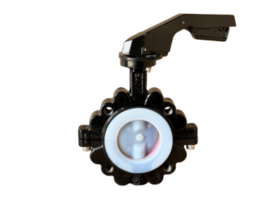
PTFE Fully Lined Butterfly Valve Lugged Split Body
Description
Technical Data Sheet
Fully Lined Fluorine Butterfly Valve – Lug Type – Split Body – Manual Operation
Product Name: Wafer Type Fully Lined Fluorine Butterfly Valve (Split Body)
Model No.: D341F46-10/16 (Example, PN10/PN16)
1. General Information
| Item | Specification |
|---|---|
| Valve Type | Concentric Butterfly Valve, Fully Lined with FEP (Fluorinated Ethylene Propylene) |
| Body Design | Split Body (Two-piece body, suitable for lug mounting, facilitates liner replacement) |
| Connection Type | Lug Type (Tapped lug holes for dead-end service), conforming to ISO 5752 / GB/T 12238 |
| Nominal Size | DN50 ~ DN600 (2″ ~ 24″) |
| Pressure Rating | PN10 / PN16 / Class 150LB |
| Medium Suitability | Strong acids, strong alkalis, organic solvents, corrosive gases/liquids |
| Operating Temperature | -20°C to +150°C (FEP long-term ≤120°C; PTFE seat suitable for wide temp range) |
| Operation | Manual (Lever Handle or Gearbox, depending on torque requirement) |
2. Design Standards & Specifications
| Item | Standard |
|---|---|
| Design & Manufacturing | GB/T 12238, API 609, MSS SP-67 |
| Face-to-Face Dimensions | ISO 5752, GB/T 12221 (Series 13/14) |
| Flange Connection Dimensions | GB/T 17241.6, HG/T 20592, ASME B16.5 (Conforming to wafer/lug type) |
| Pressure Testing | GB/T 13927, API 598 |
| Lining Quality | HG/T 4077, HG/T 4078 |
3. Main Component Materials
| Part Name | Material Specification | Remarks |
|---|---|---|
| Body | Ductile Iron (QT450-10) / Cast Steel (WCB) | Split body construction, internal/external coated with anti-corrosion paint |
| Lining | FEP (Fluorinated Ethylene Propylene / F46) | Thickness ≥3mm, fully encapsulates body passage and flange sealing faces |
| Disc | Ductile Iron / Cast Steel (FEP Lined) or Stainless Steel (FEP Overmolded) | Fully lined to prevent media contact with metal |
| Seat (Seal Ring) | PTFE (Polyetrafluoroethylene) | Pure PTFE or Reinforced PTFE; Replaceable, provides excellent chemical resistance and low friction |
| Stem / Shaft | Stainless Steel 2Cr13 / 304 | Corrosion-resistant, pinned connection to disc |
| O-Ring / Packing | Viton (FPM) / PTFE | Stem sealing to prevent external leakage |
| Manual Operator | Cast Iron Lever / Aluminum Gearbox | Includes positioning/locking device |
4. Technical Parameters & Dimensions (Reference, PN10/PN16)
| Nominal Size (DN) | Face-to-Face (L) mm | Flange Bore Dia. (Φd) mm | Bolt Circle Dia. (D1) mm | Disc Diameter (ΦD) mm | Operator Type | Approx. Weight (kg) |
|---|---|---|---|---|---|---|
| DN50 | 43 | 125 | 110 | 102 | Lever | 5 |
| DN65 | 46 | 145 | 130 | 122 | Lever | 6.5 |
| DN80 | 46 | 160 | 150 | 138 | Lever | 8 |
| DN100 | 52 | 180 | 170 | 158 | Lever | 10 |
| DN125 | 56 | 210 | 200 | 188 | Lever | 13 |
| DN150 | 56 | 240 | 225 | 212 | Lever | 16 |
| DN200 | 60 | 295 | 280 | 268 | Gearbox | 25 |
| DN250 | 68 | 350 | 335 | 320 | Gearbox | 35 |
| DN300 | 78 | 400 | 395 | 370 | Gearbox | 50 |
| DN350 | 78 | 460 | 445 | 430 | Gearbox | 65 |
| DN400 | 102 | 515 | 495 | 482 | Gearbox | 85 |
| DN450 | 114 | 565 | 550 | 532 | Gearbox | 110 |
| DN500 | 127 | 620 | 600 | 585 | Gearbox | 140 |
| DN600 | 154 | 725 | 705 | 685 | Gearbox | 190 |
*Note: The above dimensions are based on the PN16 standard. Actual dimensions should conform to the manufacturer’s certified drawings. Lug connections comply with HG/T 20592-2009 (PN10/16).*
5. Testing & Inspection
| Test Item | Test Pressure (PN10) | Test Pressure (PN16) | Acceptance Criteria |
|---|---|---|---|
| Shell Test | 1.5 × PN = 15 bar | 1.5 × PN = 24 bar | No visible leakage, no structural damage |
| Seat Test (PTFE) | 1.1 × PN = 11 bar | 1.1 × PN = 17.6 bar | Bi-directional sealing, zero leakage (Class A per GB/T 13927) |
| Lining Spark Test | 5~20 kV depending on thickness | No breakdown |
6. Product Features & Options
-
Split Body Design: The valve body consists of two halves bolted together, facilitating the molding process of the lining and allowing for easier liner replacement or maintenance.
-
Fully Lined Construction: All wetted metal surfaces (including body passage, flange sealing faces, and disc) are encapsulated with fluoroplastic, providing excellent corrosion resistance.
-
PTFE Seat: Provides low friction coefficient, excellent chemical resistance, and long service life. Suitable for most corrosive media.
-
Lug Type Connection: The valve body has threaded lugs, allowing it to be bolted between flanges using studs. This permits dead-end service and allows removal of one side of the pipeline without affecting the other.
-
Manual Operation:
-
DN50-DN200: Standard Lever Handle, allowing variable opening positions with a locating pin to lock in fully open/closed positions.
-
DN250-DN600: Standard Gearbox with self-locking function for easy operation, complete with a handwheel.
-
-
Optional Configurations:
-
Extended stem or extended lever handle (for insulated pipelines).
-
Anti-static device (conforming to ISO 5211).
-
Position indicator or limit switch.
-
7. Installation & Maintenance Notes
-
Ensure the disc is in the closed position during installation to avoid forcing alignment.
-
Use corrosion-resistant gaskets (e.g., PTFE gaskets) for flange connections.
-
Do not force the handle when the valve is fully closed to prevent damage to the PTFE seat.
-
Regularly check the tightness of handle or gearbox mounting bolts and maintain lubrication.
Note: This data sheet provides general specifications. For specific projects, please refer to the manufacturer’s final drawings and parameters.