Cryogenic Lifting Check Valve
Description
Technical Data Sheet (TDS)
Document No.: TDS-CLCV-DN15-PN420-001
Version: V1.1
Issue Date: October 3, 2026
Prepared by: Engineering Department
1. Product Identification
| Item | Description |
|---|---|
| Product Name | Cryogenic Lifting Check Valve |
| Model / Size | DN15 (1/2″) |
| Pressure Rating | PN420 (42 MPa / 420 bar) |
| Valve Type | Lifting Check Valve (Spring-loaded, guided disc) |
| Connection Type | Butt Weld (BW) / Socket Weld (SW) / Threaded (To be confirmed) |
| Body Material | Forged Stainless Steel (Low-Temperature Service) |
| Flow Direction | Unidirectional (Arrow engraved on body) |
| Applicable Media | Cryogenic fluids: LNG, Liquid Nitrogen (LN2), Liquid Oxygen (LOX), Liquid Argon, etc. |
| Main Application | Preventing backflow in extreme low-temperature, high-pressure cryogenic systems |
2. Product Description
This product is a DN15 PN420 Cryogenic Lifting Check Valve designed specifically for high-integrity isolation in extreme low-temperature and high-pressure environments.
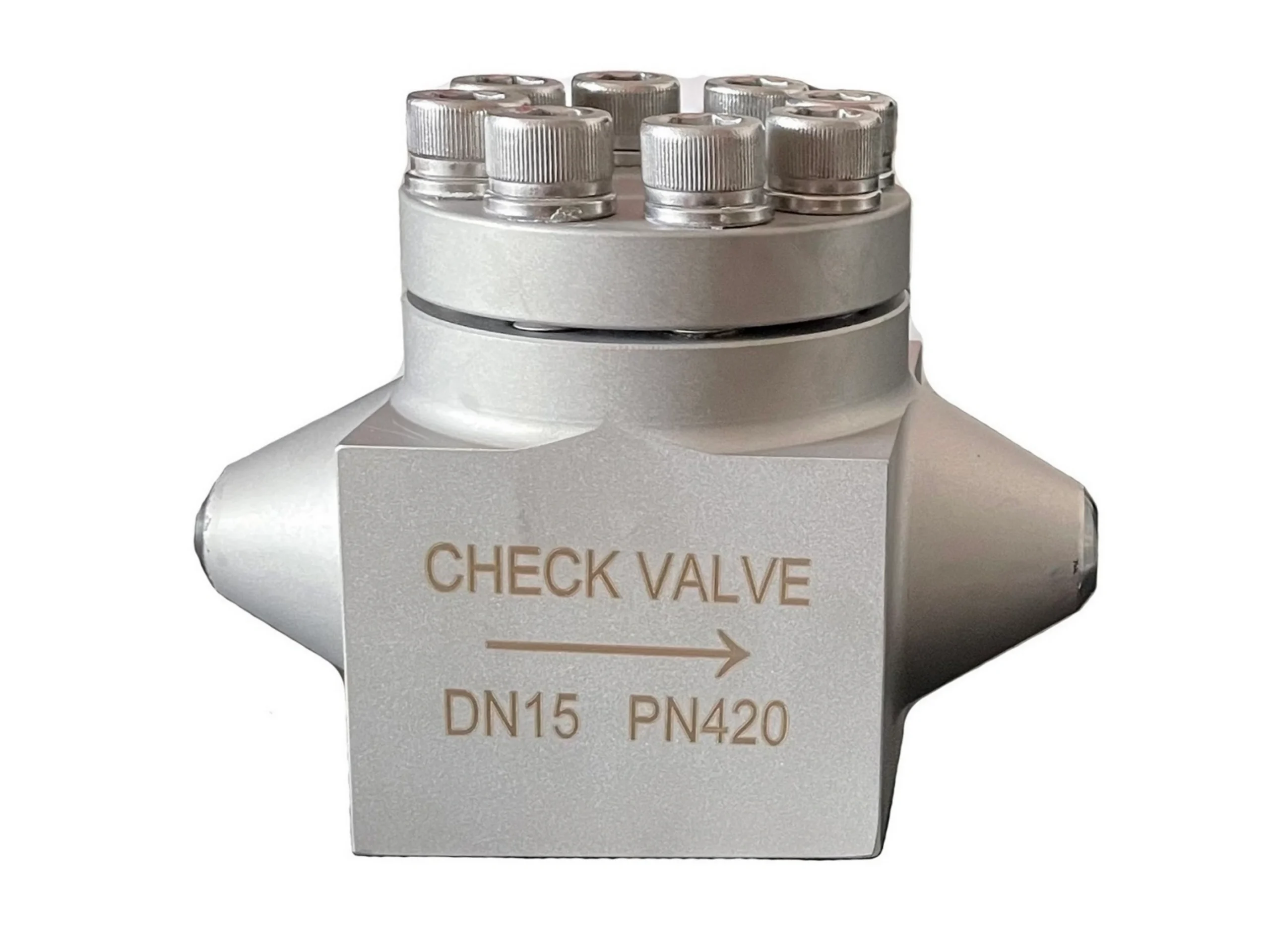
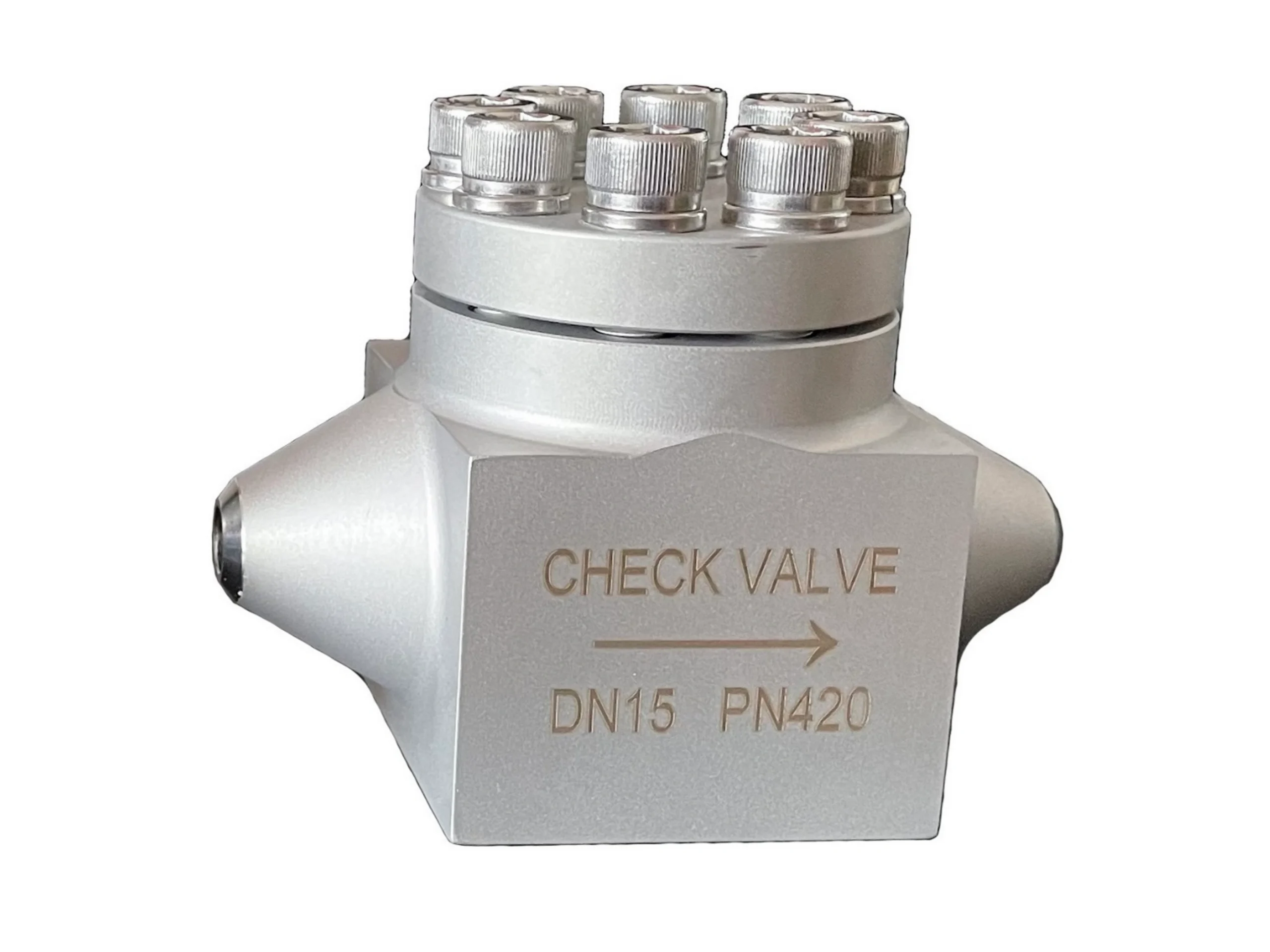
Unlike standard swing check valves, this valve utilizes a lifting (vertical) disc mechanism. The disc moves linearly along the vertical centerline, guided by the internal structure, ensuring precise alignment and tight seating even under severe thermal cycling. The heavy-duty bolted bonnet design (secured by 8 high-strength socket head cap screws) ensures structural integrity at 420 bar.
The valve body is crafted from forged stainless steel, specifically selected and heat-treated (solution annealing and cryogenic treatment) to prevent brittle fracture at cryogenic temperatures. The design ensures rapid, automatic closure to prevent reverse flow, minimizing water hammer and thermal shock in critical cryogenic pipelines.
3. Technical Parameters
| Item | Parameter |
|---|---|
| Nominal Size | DN15 (1/2″) |
| Nominal Pressure | PN420 |
| Max. Working Pressure | 42.0 MPa (420 bar) @ 38°C |
| Design Temperature Range | -196°C to +80°C (Standard Cryogenic Range) |
| Body Material | Forged Stainless Steel (ASTM A182 F304/F316) |
| Connection Standard | ASME B16.11 / ASME B16.25 / DIN 3239 |
| Pressure Test Standard | API 598 / ISO 5208 / BS 6364 |
| Leakage Class | ANSI/FCI 70-2 Class V or VI (Metal Seat) |
| Flow Direction | Unidirectional (Arrow indicated) |
4. Material Specifications
| Component | Material | Standard |
|---|---|---|
| Body / Bonnet | Forged Stainless Steel (Impact Tested at -196°C) | ASTM A182 F304/F316 |
| Disc / Trim | Stainless Steel + Hardfacing (Stellite) | ASTM A276 |
| Spring | Cryogenic-grade Stainless Steel | ASTM A313 |
| Seat / Seal | Metal-to-Metal (Lapped for cryogenic tightness) | — |
| Gasket | Spiral Wound / PTFE / Graphite (Low-temp) | — |
| Bolts / Fasteners | High-Strength Alloy Steel (Socket Head Cap) | ASTM A320 (Low Temp) |
| Surface Finish | Machined / Passivated (Silver metallic) | — |
5. Structural Features
-
Lifting Disc Design: The disc lifts vertically off the seat, guided by a central stem or cage. This prevents tilting and ensures concentric seating, which is critical for maintaining a tight seal during rapid temperature changes.
-
Cryogenic Heat Treatment: The body and bonnet undergo special cryogenic treatment to relieve stresses and stabilize the austenitic structure, preventing distortion and embrittlement at -196°C.
-
High-Pressure Forged Body: Designed for PN420 (420 bar) service, offering exceptional strength and leak-tight integrity.
-
Bolted Bonnet Construction: Secured with 8 high-tensile socket head cap screws, allowing for maintenance and inspection of the internal lifting assembly.
-
Extended Bonnet (Optional): Can be equipped with an extended bonnet to keep the packing/stem seals away from the extreme cold, preventing ice buildup and ensuring smooth operation.
-
Clear Flow Indication: The body is engraved with a prominent arrow and “CHECK VALVE” to prevent installation errors.
6. Installation & Operation
-
Pre-installation Check: Verify the valve matches the pipeline size (DN15) and pressure rating (PN420). Ensure the internal lifting disc moves freely without obstruction.
-
Flow Direction: The engraved arrow on the valve body must point in the direction of the intended forward flow.
-
Orientation: Must be installed in a vertical pipeline with flow moving upwards, or in a horizontal pipeline with the bonnet pointing vertically upwards. This ensures the lifting disc resets correctly by gravity/spring force.
-
Installation (Welding): For welded ends (BW/SW), use low-temperature welding procedures. Ensure proper cool-down to prevent heat damage to the cryogenic seals.
-
Operation: The valve operates automatically. The lifting disc opens when upstream pressure exceeds the spring force and closes instantly when flow stops or reverses.
-
Thermal Shock Warning: During system startup, open upstream valves slowly to allow gradual cooling of the valve body. Rapid cooling can cause thermal shock and damage internal components.
7. Storage & Maintenance
-
Storage Conditions: Store in a clean, dry indoor environment. Keep protective caps on the weld ends to prevent moisture and debris from entering.
-
Maintenance Cycle: Routine inspection recommended every 6 to 12 months, depending on the criticality of the system.
-
Maintenance Items: Check for external leakage at the bonnet joint. Check for frost/ice buildup around the stem area. Listen for chattering (indicating spring failure or flow instability).
-
Service: If the internal seal is compromised, the bonnet bolts can be removed to inspect or replace the disc and spring assembly. This must be done by qualified personnel in a clean, dry environment to prevent moisture ingress.
8. Inspection & Testing
| Test Item | Standard | Requirement |
|---|---|---|
| Shell Strength Test | API 598 | 1.5 times rated pressure (63 MPa), no leakage |
| High-Pressure Seat Test | API 598 | 1.1 times rated pressure (46.2 MPa), no visible leakage |
| Low-Pressure Seat Test | API 598 | 0.4–0.7 MPa air pressure, no bubbles |
| Cryogenic Test (Optional) | BS 6364 | Valve tested at -196°C to verify seat tightness and operation |
| Disc Operation Test | — | Manual check for flexible opening and closing |
9. Packaging & Transportation
| Item | Description |
|---|---|
| Packaging Type | Individual Carton / Wooden Case (Moisture-barrier wrapped) |
| Transportation Method | General Freight |
| Transportation Requirements | Prevent collision and rain exposure. Keep the valve clean and dry. |
10. Regulations & Compliance
-
Design Standard: ASME B16.34, API 602, BS 6364
-
Connection Standard: ASME B16.11, ASME B16.25
-
Testing Standard: API 598, ISO 5208, ISO 28921-1 (Cryogenic)
-
Material Certification: EN 10204 3.1 / 3.2 (Optional)
11. Version History
| Version | Date | Revision Description | Prepared/Revised by |
|---|---|---|---|
| V1.0 | October 3, 2026 | Initial Release | — |
| V1.1 | October 3, 2026 | Updated to Cryogenic Lifting Check Valve specs | — |
12. Disclaimer
The information provided in this Technical Data Sheet is based on current product design and manufacturing standards and is for reference only. Actual dimensions, weights, and performance parameters may vary depending on specific designs, material batches, and operating conditions. Users should confirm actual conditions prior to selection and installation and verify final technical parameters with the manufacturer. The manufacturer assumes no liability for direct or indirect damages arising from conditions of use beyond its control.
💡 Notes for Final Verification:
-
End Connection: Please verify if the ends are Butt Weld (BW) or Socket Weld (SW) and update Section 1 and 3 accordingly.
-
Specific Material Grade: Confirm if the body is 304 (F304) or 316 (F316) stainless steel, and if low-temperature impact testing certificates (e.g., Charpy V-Notch at -196°C) are required.
-
Temperature Range: The standard cryogenic range is -196°C (LN2). If this is for Liquid Hydrogen (-254°C) or LNG (-162°C), please adjust the temperature range in Section 3.
-
Leakage Class: For metal-seated cryogenic valves, Class V is typical, but Class VI is achievable with special lapping. Please confirm the required standard.