CPVC Lap Joint Flange Diaphragm Valve
Description
CPVC Lap Joint Flange Diaphragm Valve – Technical Data Sheet
Model:G41F-10V / G41J | Version:V1.0
1. Product Overview
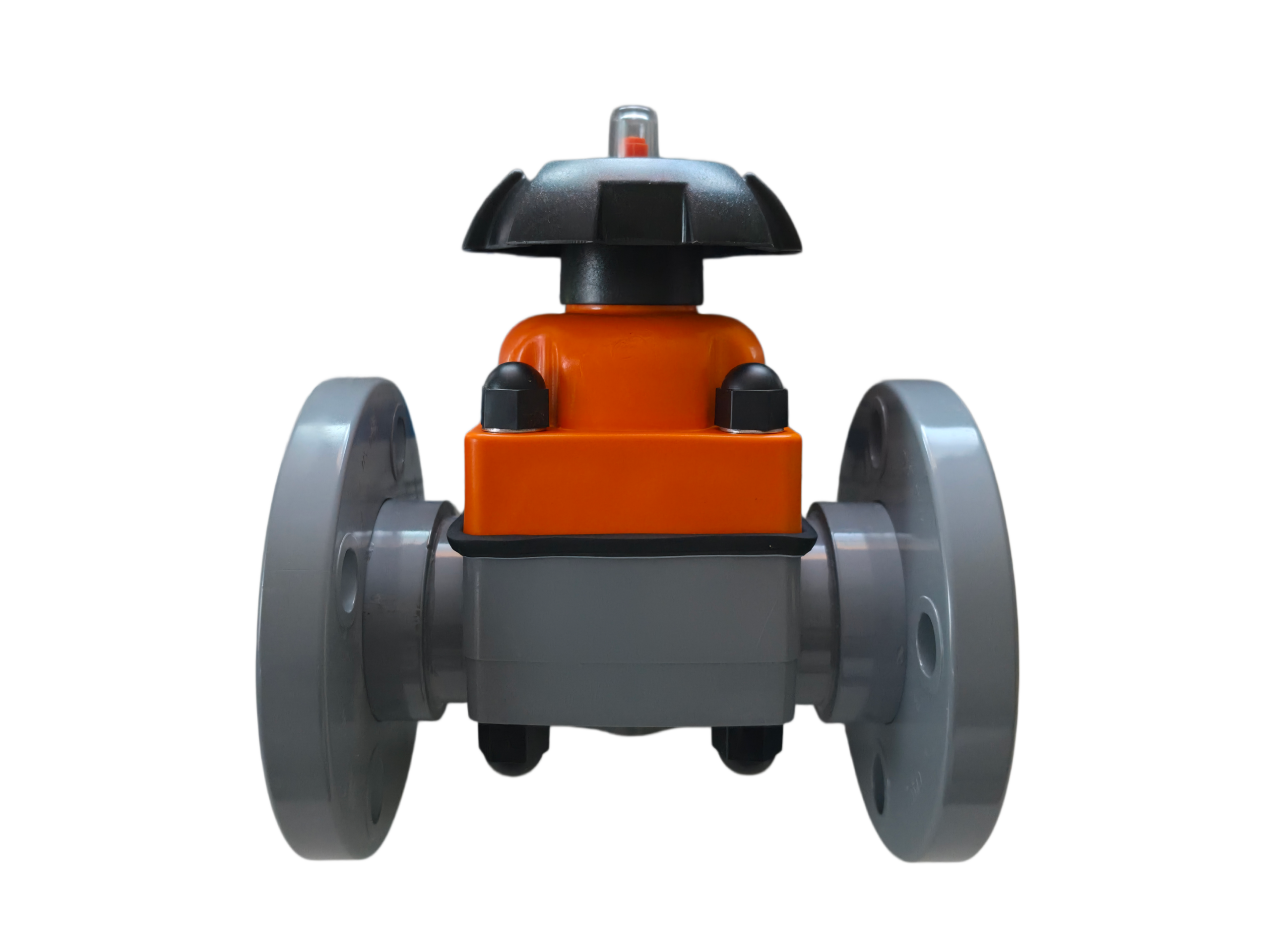
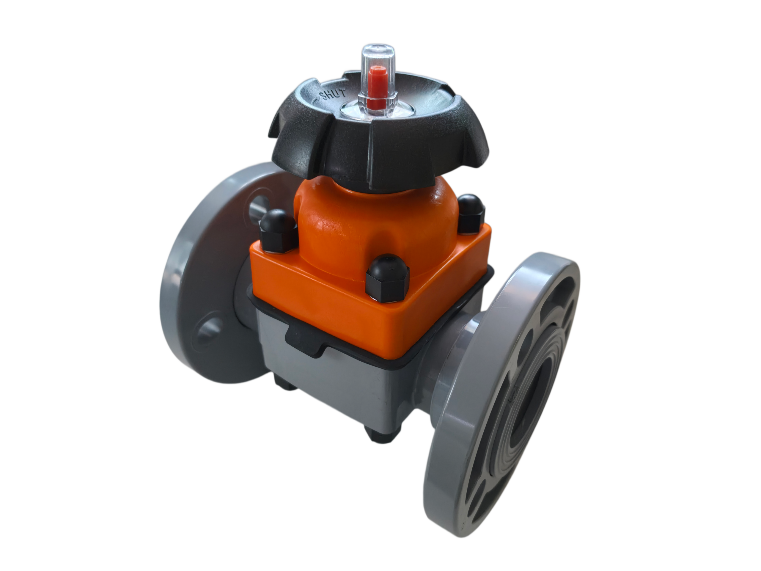
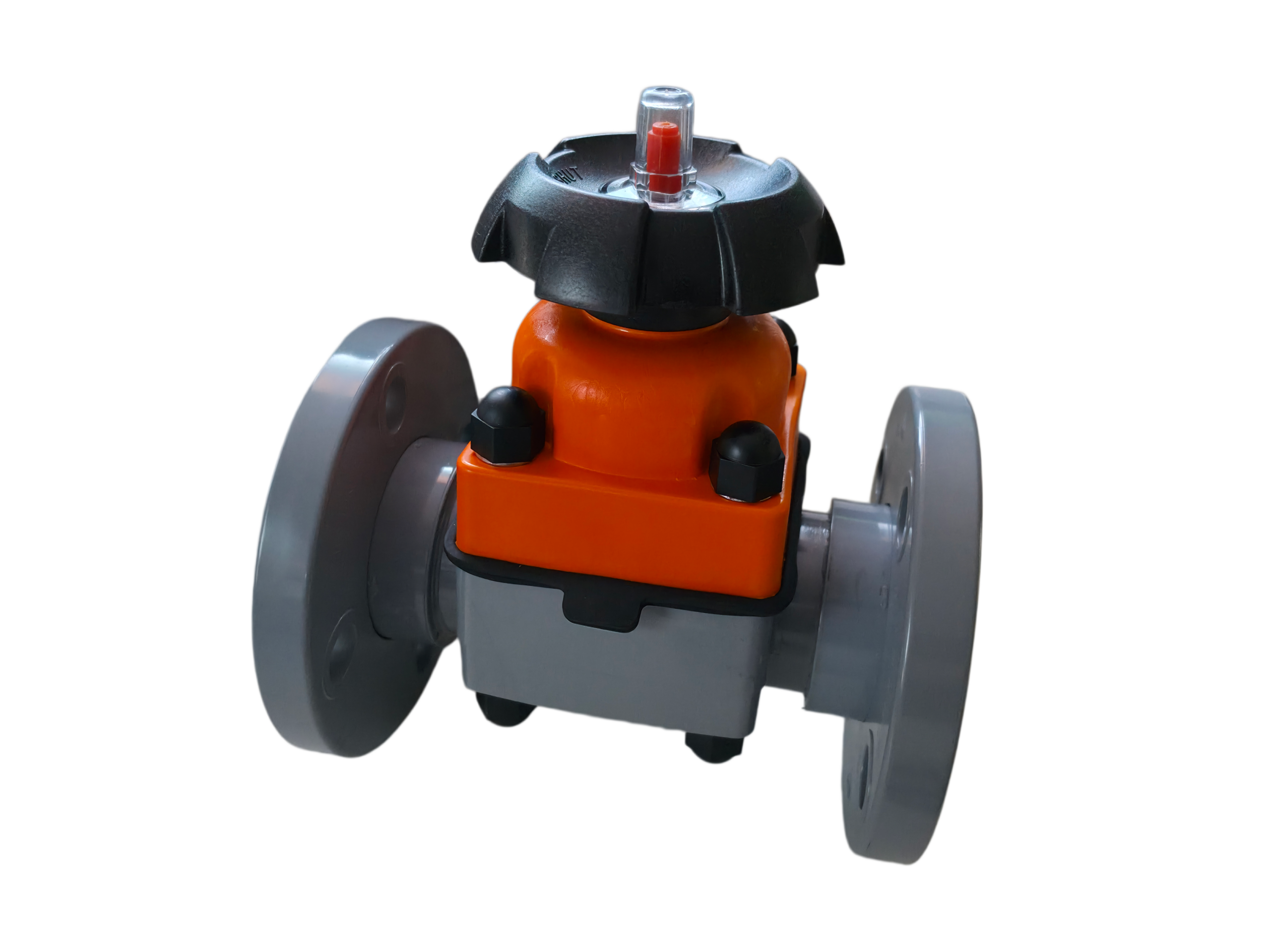
The CPVC Lap Joint Flange Diaphragm Valve is a diaphragm valve with a chlorinated polyvinyl chloride (CPVC) body and a lap joint flange connection. It adopts a diaphragm-type open/close structure, where the flexible diaphragm completely separates the body cavity from the bonnet and drive components. The valve stem, disc, and other moving parts above the diaphragm are not exposed to the medium, eliminating the need for conventional packing seals and ensuring zero external leakage.
The lap joint flange allows free rotation on the pipe end, facilitating bolt hole alignment during field installation – especially useful when flange standards differ or when installation space is limited. This valve is widely used in corrosive media conveying systems in chemical processing, water treatment, electroplating, semiconductor manufacturing, and other industries.
2. Technical Specifications
2.1 Basic Parameters
| Parameter | Value |
|---|---|
| Model | G41F-10V / G41J |
| Nominal diameter (DN) | DN15 – DN300 (½″ – 12″) |
| Nominal pressure (PN) | 0.6 MPa – 1.6 MPa (Class 150 compatible) |
| Temperature range | -40℃ to 95℃ (continuous use for CPVC) |
| Valve type | Weir type / Straight‑through type |
| Connection | Lap joint flange |
| Actuation | Manual (handwheel), pneumatic, electric |
| Design standard | HG/T 2643-94, ISO 16138:2006 |
| Flange standard | ASME B16.5 Class 150 |
2.2 CPVC Material Physical Properties
| Property | Test Method | Typical Value |
|---|---|---|
| Density | ASTM D792 | 1.51–1.52 g/cm³ |
| Tensile strength (yield, 23℃) | ASTM D638 | 52.9–61 MPa |
| Flexural strength | ASTM D790 | 72–103 MPa |
| Flexural modulus | ASTM D790 | 2620–2900 MPa |
| Notched impact strength (23℃) | ASTM D256 | 133–288 J/m |
| Heat deflection temp. (1.8 MPa) | ASTM D648 | 101–104℃ |
| Vicat softening temp. | — | 90–125℃ |
| Max. continuous use temp. | — | 95℃ |
| Max. short-term temp. | — | 110℃ |
| Flammability rating | UL94 | V-0 |
2.3 Pressure‑Temperature Derating (CPVC)
| Temperature (℃) | Temperature (℉) | Derating factor |
|---|---|---|
| 23–27 | 73–80 | 1.00 |
| 32 | 90 | 0.91 |
| 38 | 100 | 0.83 |
| 49 | 120 | 0.70 |
| 60 | 140 | 0.57 |
| 71 | 160 | 0.44 |
| 82 | 180 | 0.31 |
Example: For a valve rated 1.0 MPa at 23℃, the maximum allowable working pressure at 82℃ is approx. 0.31 MPa.
2.4 CPVC Chemical Resistance
CPVC exhibits excellent resistance to acids (including hydrochloric, sulfuric, nitric), alkalis, salt solutions, and many oxidising agents at both ambient and elevated temperatures. The increased chlorine content gives significantly better chemical stability than ordinary PVC. CPVC shows good resistance to most corrosive media but may swell in certain organic solvents – compatibility should be verified before use.
CPVC also has excellent flame‑retardant, self‑extinguishing properties (UL94 V-0) and low thermal conductivity, reducing heat loss in high‑temperature piping systems.
3. Valve Structure
3.1 Component Materials
| No. | Component | Material |
|---|---|---|
| 1 | Body | CPVC |
| 2 | Bonnet | CPVC |
| 3 | Diaphragm | FEP (F46) / PFA / EPDM |
| 4 | Gasket | EPDM / IIR |
| 5 | Disc (compressor) | Cast iron with FRP / PVDF |
| 6 | Stem | Stainless steel / steel |
| 7 | Handwheel | ABS |
| 8 | Liner ring | PTFE |
| 9 | Studs, nuts, pins | Stainless steel / steel |
| 10 | Position limiter | PC / AS |
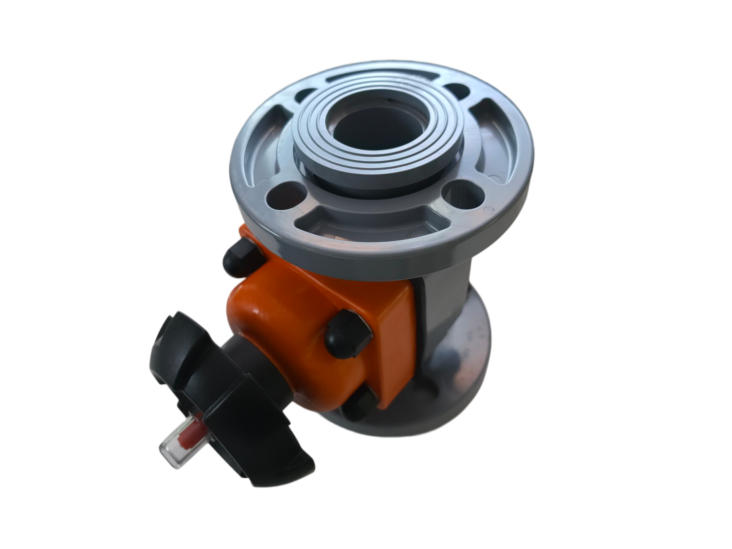
3.2 Lap Joint Flange Dimensions (ASME B16.5 Class 150)
Lap joint flanges are used with stub ends. The flange rotates freely on the pipe end for easy bolt hole alignment. Dimensions conform to ASME/ANSI B16.5, MSS SP-6 and MSS SP-25.
| DN (inch/mm) | Flange OD O (mm) | PCD (mm) | Bolt holes × dia. | Flange thickness (mm) |
|---|---|---|---|---|
| 15 (½″) | 90 | 60.3 | 4 × 15.9 | 9.6 |
| 20 (¾″) | 100 | 69.9 | 4 × 15.9 | 11.2 |
| 25 (1″) | 110 | 79.4 | 4 × 15.9 | 12.7 |
| 32 (1¼″) | 115 | 88.9 | 4 × 15.9 | 14.3 |
| 40 (1½″) | 125 | 98.4 | 4 × 15.9 | 15.9 |
| 50 (2″) | 150 | 120.7 | 4 × 19.0 | 17.5 |
| 65 (2½″) | 180 | 139.7 | 4 × 19.0 | 20.7 |
| 80 (3″) | 190 | 152.4 | 4 × 19.0 | 22.3 |
| 100 (4″) | 230 | 190.5 | 8 × 19.0 | 22.3 |
3.3 Overall Dimensions (reference)
| DN | Length L (mm) | Height H (approx., mm) |
|---|---|---|
| 15 | 105–125 | 110–130 |
| 20 | 105–125 | 120–150 |
| 25 | 125–145 | 130–160 |
| 32 | 135–160 | 145–165 |
| 40 | 145–180 | 180–200 |
| 50 | 180–210 | 210–230 |
| 65 | 210–250 | 250–280 |
| 80 | 250–280 | 280–310 |
| 100 | 280–350 | 340–350 |
4. Operating Principle
When the handwheel is turned, the stem nut drives the stem up or down. The disc (compressor) at the stem end pushes the diaphragm against the weir (for weir type) or against the flow channel wall (for straight‑through type), closing the valve. Reversing the handwheel allows the diaphragm to spring back, opening the valve.
Because the diaphragm completely isolates the body cavity from the bonnet and drive parts, the stem and disc never contact the process fluid. This ensures medium purity, prevents corrosion of the drive mechanism, and eliminates any leakage path through a conventional stuffing box.
5. Features
-
Excellent corrosion resistance – CPVC body and wetted parts resist acids, alkalis, salts, and oxidising agents.
-
Leak‑free design – No packing gland; zero external leakage.
-
Easy diaphragm replacement – Field‑replaceable wear part.
-
Lap joint flange convenience – Rotating flange simplifies bolt alignment and adapts to different flange standards.
-
Good flow capacity – Smooth flow path with low pressure drop.
-
Reliable open/close torque – Screw‑type stem provides high actuating torque.
-
Flame retardant – UL94 V-0 rating, self‑extinguishing.
-
Light weight – All‑plastic construction for easy handling and installation.
6. Elastomer / Diaphragm Performance
| Type | Material | Temp. range | Key properties |
|---|---|---|---|
| Diaphragm | FEP (F46) | ≤150℃ | Flex life ≥1200 cycles; corrosion resistance similar to PTFE |
| Diaphragm | PFA | ≤180℃ | Excellent high‑temperature and chemical resistance |
| Diaphragm | EPDM | ≤120℃ | Good acid, alkali, hot/cold water resistance |
| Gasket | EPDM/IIR | ≤120℃ | Auxiliary seal between bonnet and body |
7. Applications
-
Chemical industry – Acid, alkali, salt solutions, corrosive chemicals
-
Water treatment – Industrial water supply, pure water, cooling systems
-
Electroplating & metal finishing – Plating baths, pickling liquids, bleaching solutions
-
Semiconductor manufacturing – Ultrapure water, chemical delivery systems
-
Hydrometallurgy & fertilisers – Slurries, acid/alkali lines, residual solutions
-
Food & pharmaceutical – Sanitary applications (requires food‑grade CPVC certification)
-
Textile & leather – Bleaching, dyeing process chemicals
-
Aquaculture & marine systems – Seawater service (CPVC has excellent saltwater resistance)
Not recommended for: Certain organic solvents that may swell CPVC; continuous use above 95℃; pressures exceeding the valve’s rating.
8. Applicable Standards
-
Design & manufacture – HG/T 2643-94, ISO 16138:2006 (Industrial valves – diaphragm valves of thermoplastics materials)
-
Flange standards – ASME/ANSI B16.5 Class 150 / Class 300 (lap joint flanges and stub ends)
-
Flange manufacturing & inspection – MSS SP-6, MSS SP-25
-
CPVC material – ASTM D1784, ASME NM.3.1
9. Installation & Operation Notes
-
Ensure the pipeline is clean and free of debris before installation to avoid damaging the diaphragm sealing surface.
-
Do not use a wrench extension or over‑tighten the handwheel – risk of stem or diaphragm damage.
-
Lap joint flange stub ends must be properly socket‑welded or fused to CPVC pipe following qualified thermoplastic welding procedures.
-
Periodically inspect the diaphragm during service; replace if aged or damaged.
-
For high‑temperature service, derate the working pressure according to the pressure‑temperature derating factors.
-
Apply uniform bolt torque on lap joint flanges to avoid localised gasket compression and leakage.
-
Consider thermal expansion in CPVC piping systems – provide appropriate expansion compensation.
Remarks
The data presented above are typical values. Actual product parameters may vary depending on the specific manufacturing configuration, options, and service conditions. For critical applications, refer to the manufacturer’s official product documentation and valve selection manual, and verify chemical compatibility with the actual process medium.


