2.5 (DN65) Class 150 Wafer Butterfly Valve with Cartridge Seat
Description
2.5″ (DN65) Class 150 Wafer Butterfly Valve with Cartridge Seat – Technical Data Sheet
1. General Information
| Item | Description / Parameters |
|---|---|
| Product Name | Wafer Style Butterfly Valve (Cartridge Seat Design) |
| Nominal Size | 2.5″ (DN65) |
| Pressure Rating | Class 150LB (Approx. PN20 / 2.0 MPa) |
| Connection Type | Wafer (Flangeless, installed between two flanges) |
| Operation | Manual Lever (90° rotation, multi-position locking) |
| Seat Design | Cartridge / Replaceable Seat (Elastomer bonded to a rigid backing ring) |
| Applicable Media | Water, sewage, seawater, air, steam, natural gas, oils, and various acids/alkalis (depending on seat material) |
| Temperature Range | -20°C to +150°C (depending on elastomer material) |
2. Materials of Construction
| Part Name | Material (Reference) |
|---|---|
| Body | Ductile Iron (e.g., ASTM A536 65-45-12) or Cast Steel, with black epoxy coating |
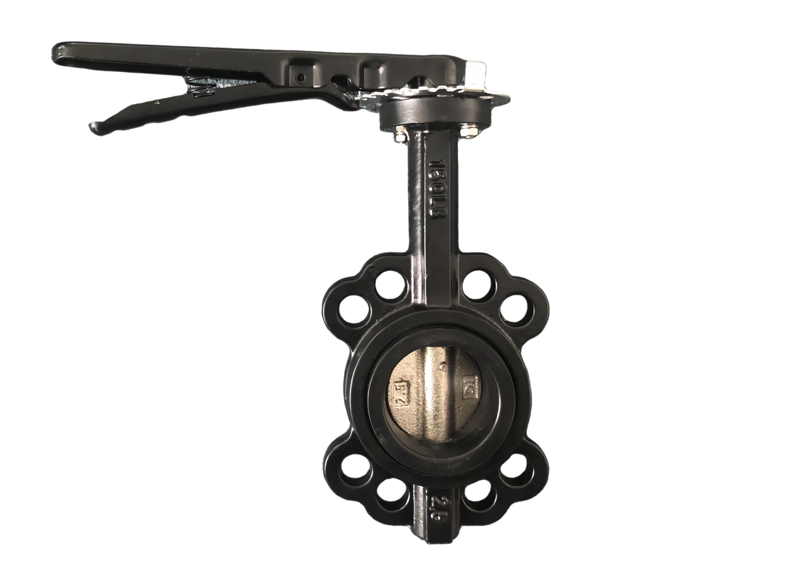
| Disc | Ductile Iron (Nickel plated or epoxy coated); Cast marks “2B” and “10” on the face |
| Stem | Stainless Steel (Typically SS416, SS304, or SS316) |
| Seat (Liner) | Cartridge Type: Elastomer (EPDM, NBR, PTFE, or FKM) bonded to a rigid backing ring (Stainless Steel or Metal) |
| Handle | Carbon Steel or Cast Iron, black painted, with ratchet locking mechanism |
| O-ring / Bushing | NBR / PTFE |
3. Design Features (Cartridge Seat)
-
Replaceable Seat Design: The cartridge seat allows for on-site or workshop replacement of the sealing element without needing to replace the entire valve body. This significantly reduces maintenance costs and downtime.
-
Dimensional Stability: Because the elastomer is bonded to a rigid backing ring, the cartridge seat resists deformation under pressure and temperature fluctuations better than a standard resilient liner.
-
Optimized Sealing: The rigid backing ensures consistent compression and interference fit against the disc, providing reliable bubble-tight sealing.
-
Material Versatility: The same valve body can accommodate different cartridge seat materials (e.g., swapping from EPDM to PTFE) to adapt to different chemical media, making it highly versatile.
4. Dimensions (Standard Reference)
Note: The 2.5″ (DN65) wafer butterfly valve is a standard industrial size. Dimensions generally follow international standards.
| Symbol | Item | Reference Dimension (mm) |
|---|---|---|
| L | Face-to-Face Length | 46 (Complies with API 609 / MSS SP-67 short pattern) |
| H1 | Center to Stem Top | Approx. 80~90 (Varies by manufacturer) |
| H2 | Center to Handle Top | Approx. 130~150 (Depends on handle length) |
| φD | Matching Flange OD | 139.7 mm (ASME B16.5 Class 150 2.5″ standard) |
| K | Bolt Circle Diameter | 114.3 mm |
| n-φd | Bolt Holes | 4 – φ15.9 mm (For 5/8″ or M16 bolts) |
| ISO 5211 | Top Mounting Flange | Typically F07/F10 (for future actuator installation) |
5. Applicable Standards
| Category | Reference Standard |
|---|---|
| Design & Manufacture | API 609 / MSS SP-67 / GB/T 12238 |
| Face-to-Face | API 609 / ISO 5752 Short Series |
| Flange Standard | ASME B16.5 Class 150 |
| Pressure Testing | API 598 |
| Shell Test | 3.0 MPa (Water) |
| Seat Test | 2.2 MPa (Water/Air) |
| Coating | Epoxy resin electrostatic coating, DFT ≥250μm |
6. Performance Specifications
| Item | Parameter |
|---|---|
| Nominal Pressure | Class 150LB (Approx. 2.0 MPa / 20 bar) |
| Max Working Pressure | 2.0 MPa (at ambient temperature) |
| Operating Torque | Typically 30~50 N·m (Cartridge seats often provide lower and more consistent torque compared to vulcanized seats) |
| Operation | 90° lever operation, multi-position locking |
| Sealing Direction | Bidirectional (Recommended to install according to the flow arrow on the body for optimal sealing) |
7. Installation & Usage Notes
-
Flange Matching: The 2.5″ (DN65) Class 150 flange has a bolt circle of 114.3mm with 4 holes. Do not mix with PN16 (DIN standard, 145mm bolt circle) flanges, as they are not interchangeable.
-
Seat Replacement: To replace the cartridge seat, the valve must be removed from the pipeline. The old cartridge is pried out, and the new cartridge is pressed evenly into the body cavity. Ensure the backing ring is fully seated.
-
Handle Clearance: Manual butterfly valves require a large rotational arc for the handle to open and close. Ensure there is adequate space around the handle during installation.
-
Valve Protection: During pipeline welding or flange installation, the valve should be in a slightly open position (approx. 10°) to prevent high welding temperatures from damaging the cartridge seat and to avoid scratching the disc with debris.
-
Regarding the “3/8” Mark: The “3/8” cast on the bottom of the valve body in the image is likely a mold number, part traceability code, or specific casting batch code from the manufacturer, not the actual size. Please refer to “2.5 inches / DN65” for procurement.