Wafer Butterfly Valve with Loose Liner
Description
– Technical Data Sheet
1. General Description
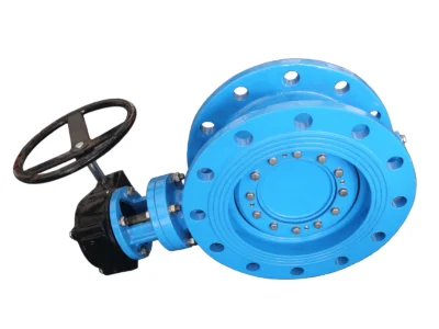
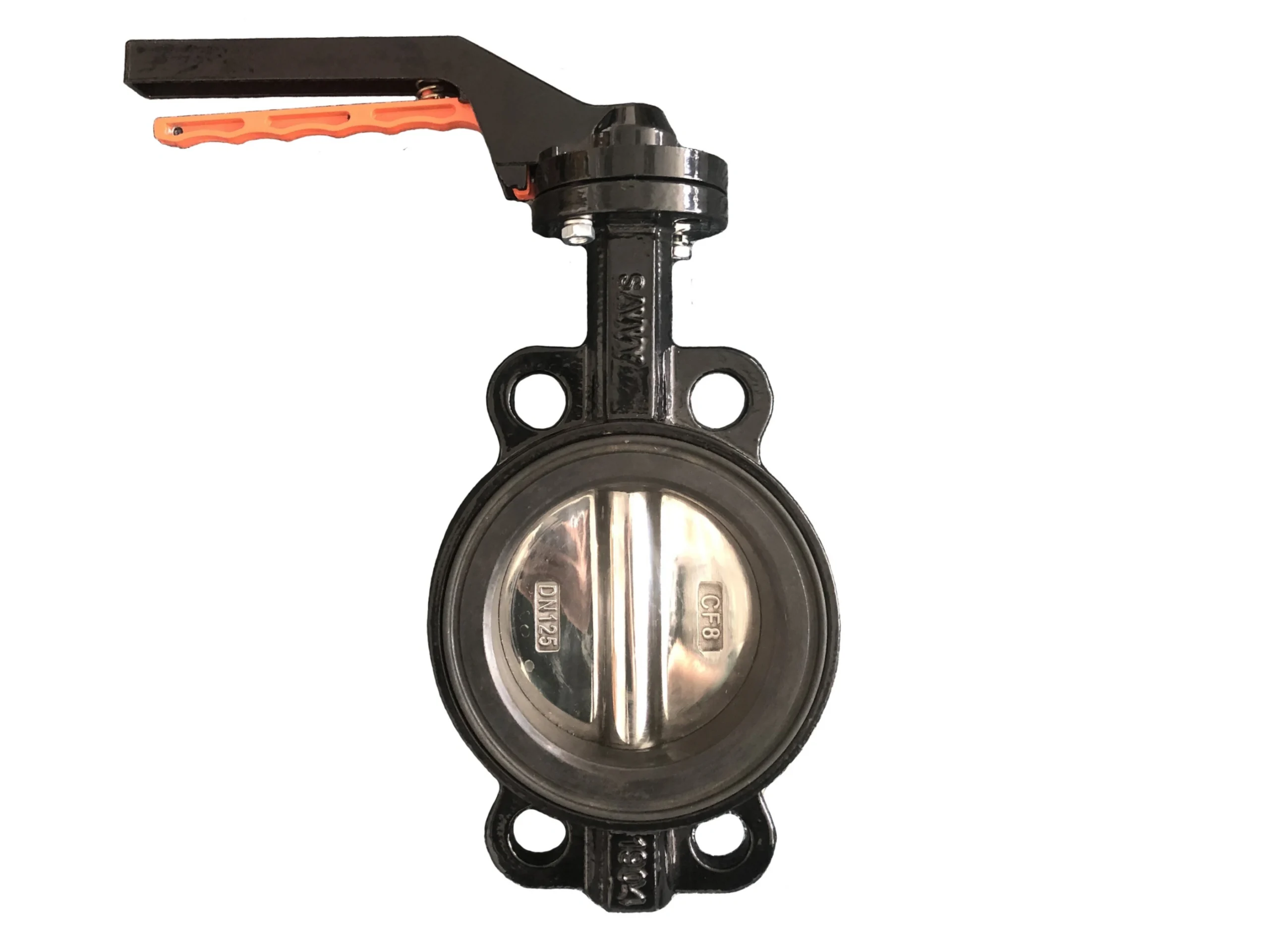
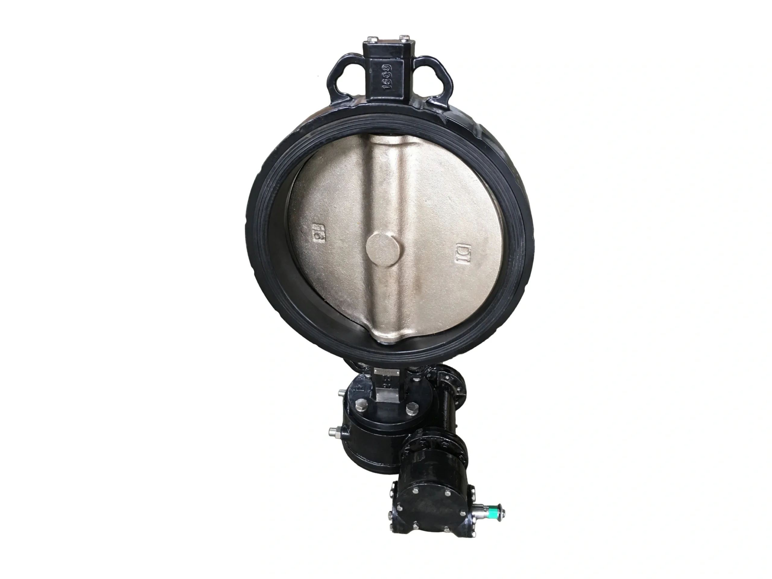
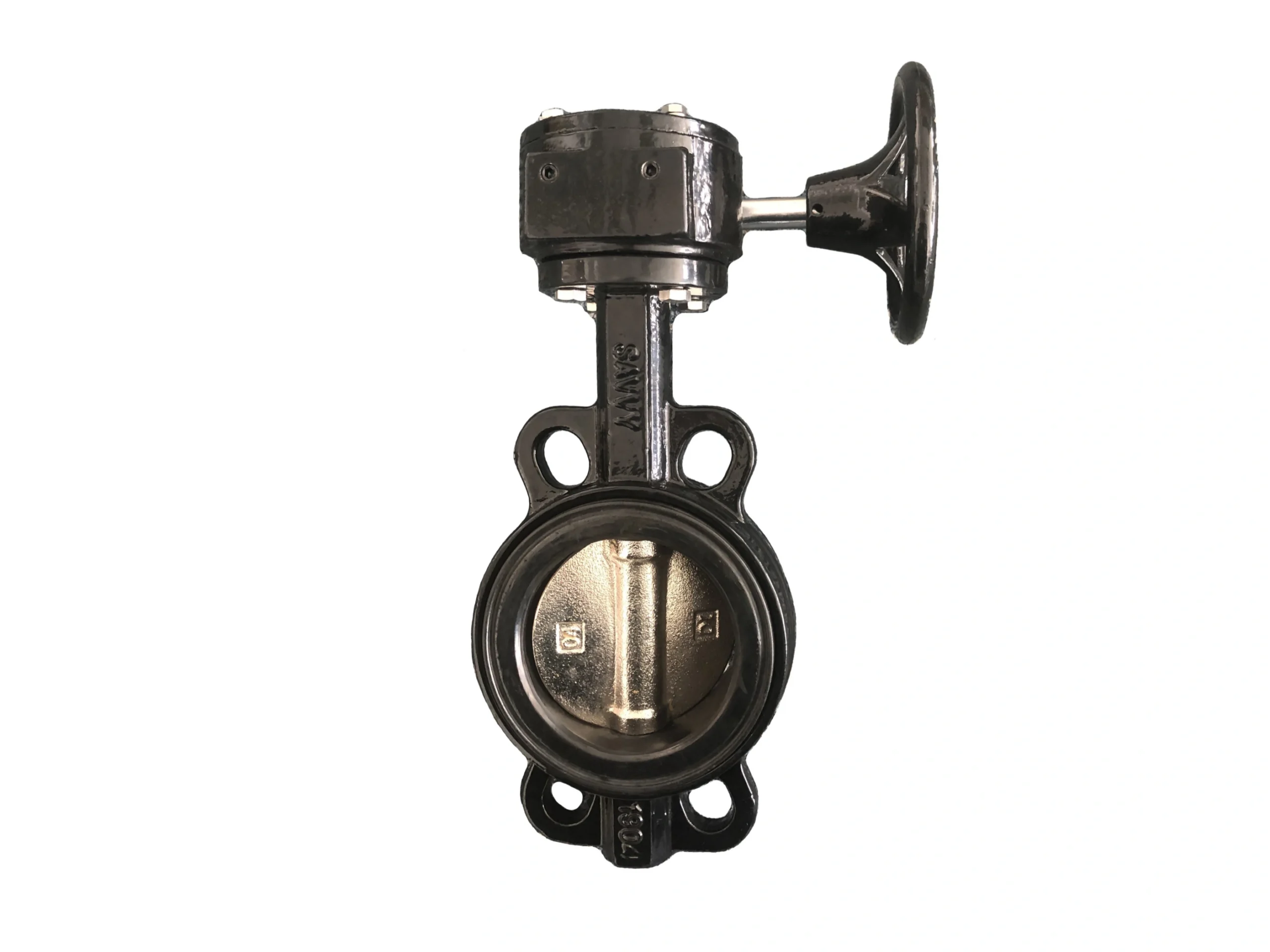
This data sheet covers concentric, wafer-style butterfly valves featuring a loose liner (replaceable seat) design. The valves are available in two primary configurations as shown: a gear-operated version (Image 1) and a lever-operated version (Images 2 & 3). Both are designed for bidirectional sealing and are suitable for a wide range of industrial applications involving water, wastewater, and other neutral or mildly corrosive media.
The “loose liner” design means the elastomeric seat is a separate, replaceable component that is not bonded or vulcanized to the valve body. This allows for easy field replacement of the seat without needing to replace the entire valve, significantly reducing maintenance costs and downtime.
2. Key Features (Loose Liner Design)
-
Replaceable Seat: The loose liner can be easily removed and replaced when worn, extending valve service life.
-
Dimensional Stability: The liner is held in place by the mating flanges and a precise groove in the body, ensuring consistent sealing and preventing liner movement during operation.
-
Simplified Maintenance: No special tools or procedures are required for seat replacement; the valve body and disc are typically reused.
-
Versatile Material Options: The loose liner can be supplied in various elastomers (EPDM, NBR, FKM, etc.) to suit different media and temperature requirements.
3. Materials of Construction
| Component | Material (Typical) |
|---|---|
| Body | Ductile Iron (ASTM A536) or Stainless Steel (CF8/CF8M) |
| Disc | Stainless Steel (CF8 / CF8M) or Nickel-Plated Ductile Iron |
| Stem | Stainless Steel (SS416, SS304, or SS316) |
| Seat / Liner | Loose Liner: EPDM, NBR, FKM (Viton), or PTFE |
| O-Ring / Bushing | NBR / PTFE |
| Operator (Lever) | Carbon Steel or Cast Iron, with locking mechanism |
| Operator (Gear) | Cast Iron or Ductile Iron Housing, with handwheel |
4. Technical Specifications
| Parameter | Lever-Operated (Images 2 & 3) | Gear-Operated (Image 1) |
|---|---|---|
| Nominal Size | DN125 (5″) | Refer to marking “16093” (likely model/size code) |
| Pressure Rating | PN16 / Class 150 | PN16 / Class 150 |
| End Connection | Wafer (flangeless) | Wafer (flangeless) |
| Design Standard | API 609 Category A | API 609 Category A |
| Face-to-Face | API 609 / ISO 5752 Series 20 | API 609 / ISO 5752 Series 20 |
| Flange Compatibility | PN10 / PN16 (DIN 2501) / ASME B16.5 Class 150 | PN10 / PN16 / ASME B16.5 Class 150 |
| Top Flange | ISO 5211 (F07 / F10 as applicable) | ISO 5211 |
| Sealing Direction | Bidirectional | Bidirectional |
| Media Temperature | -20°C to +120°C (dependent on liner material) | -20°C to +120°C (dependent on liner material) |
Note on Markings:
-
Image 2: The valve is marked “DN125” and “CF8” on the disc, indicating a 5-inch nominal size with a CF8 (304 SS) disc.
-
Image 3: The disc markings “6” and “6” (or “9”) are likely part or material traceability codes.
-
Image 1: The top marking “16093” is likely a model or size identifier; the actual size should be confirmed with the manufacturer.
5. Dimensions (Reference for DN125 / 5″)
| Symbol | Description | Dimension (mm) |
|---|---|---|
| L | Face-to-Face Length | 56 (per API 609 short pattern) |
| φK | Flange Bolt Circle (PN16) | 210 |
| n-φd | Bolt Holes (PN16) | 8 – φ18 |
| φK | Flange Bolt Circle (Class 150) | 215.9 |
| n-φd | Bolt Holes (Class 150) | 8 – φ22 |
| H1 | Center to Top Flange | ~127 (varies by manufacturer) |
Weight (Theoretical): Approximately 5.0 kg for a standard DN125 loose-liner wafer valve with lever operator.
6. Performance Data
| Parameter | Value |
|---|---|
| Nominal Pressure | PN16 (1.6 MPa) / Class 150 (2.0 MPa) |
| Shell Test Pressure | 2.4 MPa (PN16) / 3.0 MPa (Class 150) |
| Seat Test Pressure | 1.76 MPa (PN16) / 2.2 MPa (Class 150) |
| Leakage Class | Bubble-tight (Soft-seated) |
| Operating Torque | Consult manufacturer (typically 30-60 N·m for DN125) |
7. Applicable Standards
| Category | Standard |
|---|---|
| Design & Manufacture | API 609 Category A / MSS SP-67 |
| Face-to-Face | API 609 / ISO 5752 Series 20 / EN 558 |
| Flange Connection | ASME B16.5 Class 150 / DIN 2501 PN10-16 |
| Top Mounting | ISO 5211 |
| Pressure Testing | API 598 |
| Coating | Epoxy resin electrostatic coating (min. 250 μm) |
8. Installation & Maintenance
-
Flange Matching: Ensure the mating flange bolt pattern matches the valve’s requirement (PN16 or Class 150). The wafer design requires through-bolts or studs for installation.
-
Valve Position: For optimal sealing, install the valve with the stem upstream. The valve can be installed in any orientation, but ensure adequate clearance for the handle or handwheel.
-
Liner Protection: During installation, keep the valve in a slightly open position (~10°) to prevent damage to the loose liner from sharp flange edges or weld spatter.
-
Seat Replacement: To replace the loose liner, remove the valve from the pipeline, open the disc, and carefully pry out the old liner. Clean the body groove, insert the new liner, and ensure it is seated evenly before reinstalling.
-
Actuation: The ISO 5211 top flange allows for direct mounting of manual, pneumatic, or electric actuators. Ensure the actuator output torque is sufficient for the valve’s operating torque.
9. Ordering Information
To ensure correct supply, please specify:
-
Nominal size and pressure rating (e.g., DN125, PN16).
-
Body material (e.g., Ductile Iron, CF8, CF8M).
-
Disc material (e.g., CF8, CF8M, Nickel-plated).
-
Liner material (e.g., EPDM, NBR, FKM).
-
Operator type (Lever, Gearbox, Actuator).
-
Any special requirements (e.g., WRAS approval, high-temperature service).
Disclaimer: This data sheet is compiled based on standard industry specifications and visual inspection of the provided images. Actual dimensions, materials, and performance data may vary by manufacturer. For critical applications, please verify all parameters with the original equipment manufacturer (OEM).