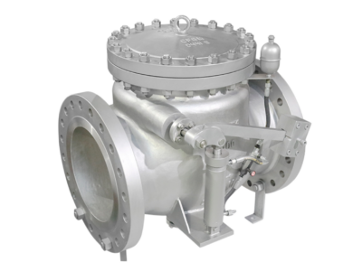
14″ Class 125 Bronze-Seated Swing Check Valve
Description
Technical Data Sheet: 14″ Class 125 Bronze-Seated Swing Check Valve
1. Product Overview
This product is a 14-inch, Class 125 bronze-seated swing check valve with a bolted bonnet and flanged ends. It is designed to prevent reverse flow in waterworks and industrial pipeline systems. The valve features a cast iron or ductile iron body with a renewable bronze seat ring, providing excellent corrosion resistance and reliable sealing performance. The valve is manufactured in accordance with AWWA C508 and MSS SP-71 standards.
2. Technical Specifications
| Item | Parameter |
|---|---|
| Valve Type | Swing Check Valve (Single Disc, Non-Assisted) |
| Nominal Size | NPS 14 (DN 350) |
| Pressure Rating | Class 125 / 150 (ASME B16.1) |
| Design Standard | AWWA C508 / MSS SP-71 |
| Face-to-Face Standard | ASME B16.10 |
| Flange Standard | ASME B16.1 (Class 125) |
| Working Pressure | 150 psi (10.3 bar) for 14″ and above; 200 psi available |
| Temperature Range | -10°C to +200°C (14°F to 392°F) |
| Applicable Media | Water, Steam, Oil, Gas, and other non-corrosive fluids |
Note: For 14″–24″ sizes, the standard working pressure per AWWA C508 is 150 psi, with a shell test pressure of 300 psi. Some manufacturers offer 200 psi rated valves with 400 psi shell test.
3. Main Component Materials
| Component | Material | Standard / Grade |
|---|---|---|
| Body / Bonnet | Cast Iron / Ductile Iron | ASTM A126 Class B / ASTM A536 |
| Disc | Cast Iron / Ductile Iron or Bronze | ASTM A126 / ASTM A536 / ASTM B62 |
| Seat Ring | Bronze | ASTM B62 C83600 (CC491K) |
| Hinge Pin | Stainless Steel | 316 Stainless Steel |
| Bushings | Bronze | Low-zinc bronze |
| Fasteners | Stainless Steel | ASTM A276 Grade 304 |
| Coating | Fusion-Bonded Epoxy (Optional) | Per AWWA C550 |
4. Design & Structural Features
4.1 Full Waterway Design
The valve is designed to provide a “Full Waterway” per MSS SP-71, Type I. When fully open, the waterway cross-sectional area at any point is at least equal to the area of a circle whose diameter is the nominal valve size. This ensures minimal pressure drop and low flow resistance.
4.2 Swing Disc Mechanism
The valve uses a single-disc, swing-type design with a lever arm mechanism. The disc automatically opens by media flow pressure and closes by disc weight and backflow. The hinge pin is mounted horizontally above the pipe centerline, ensuring proper seating and minimal water hammer.
4.3 Bronze Seat Ring
The seat ring is made of ASTM B62 C83600 bronze alloy, providing excellent corrosion resistance and wear resistance. The bronze seat mates with the metal disc for reliable, galling-resistant sealing.
4.4 Bolted Bonnet
The bolted bonnet design allows for easy access to internal components for maintenance and repair without removing the valve from the pipeline.
4.5 Corrosion-Resistant Construction
The clapper arm is made of high-strength bronze, and the hinge pin is made of 316 stainless steel. Corrosion-resistant bearings, bushings, and washers are used to reduce wear and extend operating life.
5. Dimensional Reference
ASME Class 125 / NPS 14
| Item | Value |
|---|---|
| Face-to-Face (Flanged) | 31.00″ (787 mm) |
| Flange Outer Diameter (OD) | 21.00″ (533 mm) |
| Bolt Circle (BC) | 18.75″ (476 mm) |
| Number of Bolt Holes | 12 |
| Bolt Hole Diameter | 1⅛” (28.6 mm) |
| Approximate Weight | 950 lbs (431 kg) |
Note: Face-to-face dimensions are per ASME B16.10 for Class 125 cast iron flanged valves. Flange dimensions are per ASME B16.1 Class 125.
6. Pressure Test
| Test Item | Test Pressure | Test Medium | Duration |
|---|---|---|---|
| Shell Test | 300 psi (2 × 150 psi) | Clean Water | ≥ 10 min |
| Seat Test | 150 psi (1 × working pressure) | Clean Water | ≥ 2 min |
Acceptance Criteria: No visible leakage during shell test; seat leakage rate complies with AWWA C508 requirements (drip-tight shut-off).
7. Installation Requirements
-
Orientation: The valve must be installed with the hinge pin parallel to the horizontal plane and above the pipe centerline. Incorrect installation may result in binding, high head loss, or the disc hanging open.
-
Flow Direction: Install with flow horizontal or flow upward if installed vertically. The arrow on the body must match the flow direction.
-
Clearance: Ensure adequate space above the valve for disc swing clearance.
-
Pipe Support: Due to the heavy weight of NPS 14 valves (approximately 950 lbs), pipe supports should be installed on both sides to prevent stress on the valve body.
-
Flange Bolting: Use appropriate gaskets and bolt torque values for Class 125 cast iron flanges.
8. Applications
-
Water supply and distribution systems
-
Wastewater and sewage treatment plants
-
Fire protection systems
-
HVAC and pumping stations
-
Industrial pipelines requiring backflow prevention
9. Ordering Information
Please provide the following information when ordering:
-
Nominal Size (NPS / DN)
-
Pressure Rating (Class 125 / 150)
-
Connection Type (Flanged per ASME B16.1)
-
Seat Type (Bronze Metal-Seated)
-
Special Requirements (Epoxy Coating, NSF/ANSI 61 Certification, Lever & Weight, etc.)